
Installation Instructions
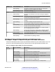

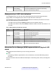


Table Of Contents
- Contents
- Chapter 1: Introduction
- Chapter 2: New in this document
- Chapter 3: Hardware models
- Chapter 4: Preinstallation checklist
- Chapter 5: Installing the Avaya Virtual Services Platform 7200 Series
- Installation checklist
- Installation fundamentals
- Electrostatic discharge
- Technical specifications
- Package contents
- Installing a power supply
- Removing a power supply
- Installing a fan module
- LED state definitions
- Installing the switch in an equipment rack
- Cable requirements for the VSP 7200
- Installation and removal of transceivers
- Console port pin assignments
- 40GBASE-QSFP+ ports
- Software limitations
- Chapter 6: Translations of safety messages

Figure 13: Blue release latch
•
Blue locking mechanism—This locking mechanism is on the rack rails. They have a blue label
with an arrow.
Figure 14: Blue locking mechanism
- When you first install the slide rails and you fully extended the rail, you can lift the locking
mechanism to release the rail so it can slide back into the main part of the unit.
- When you install the switch in a rack and then pull the switch out, this mechanism
automatically locks the slide rail in a fully extended position.
• Retaining latch—These latches are on the front and back of the slide rails. Use the hooks on
these latches to wrap around the frame of the equipment rack and lock the rail into place.
Installing the Avaya Virtual Services Platform 7200 Series
November 2016 Installing the Avaya VSP 7200 Series 50
Comments on this document? infodev@avaya.com