
Installation Instructions
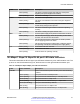

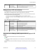


Table Of Contents
- Contents
- Chapter 1: Introduction
- Chapter 2: New in this document
- Chapter 3: Hardware models
- Chapter 4: Preinstallation checklist
- Chapter 5: Installing the Avaya Virtual Services Platform 7200 Series
- Installation checklist
- Installation fundamentals
- Electrostatic discharge
- Technical specifications
- Package contents
- Installing a power supply
- Removing a power supply
- Installing a fan module
- LED state definitions
- Installing the switch in an equipment rack
- Cable requirements for the VSP 7200
- Installation and removal of transceivers
- Console port pin assignments
- 40GBASE-QSFP+ ports
- Software limitations
- Chapter 6: Translations of safety messages

Figure 8: Short rear bracket
•
Extension bracket—This bracket connects to the rack rail to lengthen it for a 600mm-900mm
configuration.
• Long rear bracket—This bracket replaces the short rear bracket to modify the slide rail for a
600mm-900mm configuration.
The following figure shows the extension bracket and the long rear bracket. Both are used for a
600mm–900mm configuration.
Figure 9: Extension and long rear brackets
Locks and latches
This section describes the locks and latches on the rails and where they are located.
Installing the switch in an equipment rack
November 2016 Installing the Avaya VSP 7200 Series 47
Comments on this document? infodev@avaya.com