
Installation Instructions

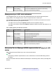


Table Of Contents
- Contents
- Chapter 1: Introduction
- Chapter 2: New in this document
- Chapter 3: Hardware models
- Chapter 4: Preinstallation checklist
- Chapter 5: Installing the Avaya Virtual Services Platform 7200 Series
- Installation checklist
- Installation fundamentals
- Electrostatic discharge
- Technical specifications
- Package contents
- Installing a power supply
- Removing a power supply
- Installing a fan module
- LED state definitions
- Installing the switch in an equipment rack
- Cable requirements for the VSP 7200
- Installation and removal of transceivers
- Console port pin assignments
- 40GBASE-QSFP+ ports
- Software limitations
- Chapter 6: Translations of safety messages

Rails
The following figure shows a slide rail in the default configuration for a 300mm-600mm equipment
rack. This configuration comes with the short rear bracket installed. The slide rail actually consists of
two separate rails that slide into each other:
• Rack rail—This rail is the main component that connects to the equipment rack.
• Chassis rail—This rail is embedded in the rack rail. Later, the installation instructions explain
how to detach these two rails and install the chassis rail onto your switch.
Figure 7: Rails
Brackets
There are three different brackets:
•
Short rear bracket—The slide rail kit comes with this bracket installed for the 300mm-600mm
default configuration.
Installing the Avaya Virtual Services Platform 7200 Series
November 2016 Installing the Avaya VSP 7200 Series 46
Comments on this document? infodev@avaya.com