
Installation Instructions

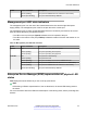


Table Of Contents
- Contents
- Chapter 1: Introduction
- Chapter 2: New in this document
- Chapter 3: Hardware models
- Chapter 4: Preinstallation checklist
- Chapter 5: Installing the Avaya Virtual Services Platform 7200 Series
- Installation checklist
- Installation fundamentals
- Electrostatic discharge
- Technical specifications
- Package contents
- Installing a power supply
- Removing a power supply
- Installing a fan module
- LED state definitions
- Installing the switch in an equipment rack
- Cable requirements for the VSP 7200
- Installation and removal of transceivers
- Console port pin assignments
- 40GBASE-QSFP+ ports
- Software limitations
- Chapter 6: Translations of safety messages

Warning:
If you pull the switch all the way out on the slide rails, there is a danger of the rack tipping over.
For more information and guidelines, see Important notice about rack safety on page 74.
Inventory of slide components
This section describes the slide components and their features.
The shipping carton contains the following components:
•
Two 300mm-600mm slides (default configuration)
• Two extension brackets for the 600mm-900mm configuration
• Two long rear brackets for the 600mm-900mm configuration
• Bag of screws
Figure 6: Shipping components
Installing the switch in an equipment rack
November 2016 Installing the Avaya VSP 7200 Series 45
Comments on this document? infodev@avaya.com