
Installation Instructions
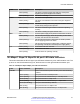

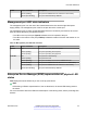


Table Of Contents
- Contents
- Chapter 1: Introduction
- Chapter 2: New in this document
- Chapter 3: Hardware models
- Chapter 4: Preinstallation checklist
- Chapter 5: Installing the Avaya Virtual Services Platform 7200 Series
- Installation checklist
- Installation fundamentals
- Electrostatic discharge
- Technical specifications
- Package contents
- Installing a power supply
- Removing a power supply
- Installing a fan module
- LED state definitions
- Installing the switch in an equipment rack
- Cable requirements for the VSP 7200
- Installation and removal of transceivers
- Console port pin assignments
- 40GBASE-QSFP+ ports
- Software limitations
- Chapter 6: Translations of safety messages

SFP and SFP+ port LED state indicators
This section describes the transceiver port LED state indicators by color and fluctuation cues. These
ports use the LED on the left side of the port (Link/Act) to indicate whether or not the link is
established and if a transceiver is present and active.
The LED on the right side of the port (In Use) indicates the operating speed of the transceiver.
Table 13: SFP/SFP+ port LED state indicators
Label Color and Status Description
Link/Act Off There is no transceiver present and the port is administratively
enabled.
Amber (steady) The port is actively transmitting, but there is no link. This
indicates a local fault.
Amber (blinking) The port received a remote fault indicator (RFI).
Green (steady) The port has established a link.
Green (blinking) The port has established a link and there is data activity.
Green (slow blinking) The port is administratively disabled.
In Use Off Operating at low speed (10 Mbps if SFP, 100 Mbps if SFP+)
Green (steady) Operating at mid speed (100 Mbps if SFP, 1 Gbps if SFP+)
Green (blinking) Operating at high speed (1 Gbps if SFP, 10 Gbps if SFP+)
QSFP+ port LED state indicators
This section describes the transceiver port LED state indicators by color and fluctuation cues. The
Link/Act) indicates whether or not the link is established and if a transceiver is present and active.
Each 40 Gb QSFP+ port can be channelized into 4 x 10 Gb ports. To support channelization, each
QSFP+ port has four status LEDs under the port. When the QSFP+ port is not channelized, only the
LED on the left side of the port is used.
Table 14: SFP/SFP+ port LED state indicators
Label Color and Status Description
Link/Act Off There is no transceiver present and the port is administratively
enabled.
Amber (steady) The port is actively transmitting, but there is no link. This
indicates a local fault.
Amber (blinking) The port received a remote fault indicator (RFI).
Green (steady) The port has established a link.
Table continues…
Installing the Avaya Virtual Services Platform 7200 Series
November 2016 Installing the Avaya VSP 7200 Series 42
Comments on this document? infodev@avaya.com