
Admin Guide


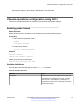


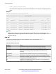


Table Of Contents
- Contents
- Chapter 1: Introduction
- Chapter 2: New in this document
- Chapter 3: Basic administration
- Chapter 4: System startup fundamentals
- Chapter 5: Boot parameter configuration using ACLI
- Chapter 6: Run-time process management using ACLI
- Chapter 7: Chassis operations
- Chassis operations fundamentals
- Chassis operations configuration using ACLI
- Enabling jumbo frames
- Configuring port lock
- Configuring SONMP
- Viewing the topology message status
- Associating a port to a VRF instance
- Configuring an IP address for the management port
- Configuring Ethernet ports with Autonegotiation
- Enabling channelization
- Configuring serial management port dropping
- Controlling slot power
- Enabling or disabling the USB port
- Chassis operations configuration using EDM
- Editing system information
- Editing chassis information
- Configuring system flags
- Configuring channelization
- Configuring basic port parameters
- Viewing the boot configuration
- Configuring boot flags
- Enabling Jumbo frames
- Configuring the date and time
- Associating a port to a VRF instance
- Configuring CP Limit
- Configuring an IP address for the management port
- Editing the management port parameters
- Configuring the management port IPv6 interface parameters
- Configuring management port IPv6 addresses
- Auto reactivating the port of the SLPP shutdown
- Editing serial port parameters
- Enabling port lock
- Locking a port
- Viewing power information
- Viewing power status on VSP 8400
- Viewing fan information
- Viewing topology status information
- Viewing the topology message status
- Configuring a forced message control pattern
- Chapter 8: Hardware status using EDM
- Chapter 9: Domain Name Service
- Chapter 10: Licensing
- Chapter 11: Network Time Protocol
- Chapter 12: Secure Shell
- Secure Shell fundamentals
- Secure Shell configuration using ACLI
- Downloading the software
- Enabling the SSHv2 server
- Changing the SSH server authentication mode
- Setting SSH configuration parameters
- Verifying and displaying SSH configuration information
- Connecting to a remote host using the SSH client
- Generating user key files
- Managing an SSL certificate
- Disabling SFTP without disabling SSH
- Enabling SSH rekey
- Configuring SSH rekey data-limit
- Configuring SSH rekey time-interval
- Displaying SSH rekey information
- Downgrading or upgrading from releases that support different key sizes
- Secure Shell configuration using Enterprise Device Manager
- Chapter 13: System access
- System access fundamentals
- System access configuration using ACLI
- Enabling ACLI access levels
- Changing passwords
- Configuring an access policy
- Specifying a name for an access policy
- Allowing a network access to the switch
- Configuring access policies by MAC address
- System access security enhancements
- Displaying the boot config flags status
- Enabling enhanced secure mode
- Creating accounts for different access levels
- Deleting accounts in enhanced secure mode
- Configuring a password for a specific user
- Returning the system to the factory defaults
- Configuring the password complexity rule
- Configuring the password length rule
- Configuring the change interval rule
- Configuring the reuse rule
- Configuring the maximum number of sessions
- Configuring the maximum age rule
- Configuring the pre- and post-notification rule
- System access configuration using EDM
- Chapter 14: ACLI show command reference
- Access, logon names, and passwords
- Basic switch configuration
- Current switch configuration
- CLI settings
- Ftp-access sessions
- Hardware information
- NTP server statistics
- Power summary
- Power information for power supplies
- System information
- System status (detailed)
- Telnet-access sessions
- Users logged on
- Port egress COS queue statistics
- CPU queue statistics
- Chapter 15: Port numbering and MAC address assignment reference
- Chapter 16: Supported standards, RFCs, and MIBs
- Glossary

show autotopology nmm-table
Unless the witch is physically connected to other devices in the network, this topology will be
blank.
Example
Switch:1(config)#show autotopology nmm-table
==========================================================================================
Topology Table
==========================================================================================
Local Rem
Port IpAddress SegmentId MacAddress ChassisType BT LS CS Port
------------------------------------------------------------------------------------------
0/0 10.139.43.35 0x000000 b0adaa419c00 VSP8404 12 Yes HtBt 0/0
2/1 10.139.43.20 0x010102 b0adaa404004 VSP8404 12 Yes HtBt 1/2/1
2/2/1 10.139.43.30 0x040102 b0abba404002 VSP8404 12 Yes HtBt 3/2/2
2/2/3 10.139.43.40 0x000102 aa12ea404003 VSP9012 12 Yes HtBt 4/1
Note:
When a peer switch is running an older software version that does not include support for
SONMP hello messages with channelization information, it can only show the slot/port. It cannot
show the sub-port.
Job aid
The following table describes the column headings in the command output for show
autotopology nmm-table.
Table 30: Variable definitions
Variable Value
Local Port Specifies the slot and port that received the topology message.
IpAddress Specifies the IP address of the sender of the topology message.
SegmentId Specifies the segment identifier of the segment from which the remote
agent sent the topology message. This value is extracted from the
message.
MacAddress Specifies the MAC address of the sender of the topology message.
ChassisType Specifies the chassis type of the device that sent the topology message.
BT Specifies the backplane type of the device that sent the topology message.
The switch uses a backplane type of 12.
LS Indicates if the sender of the topology message is on the same Ethernet
segment as the reporting agent.
Table continues…
Chassis operations
January 2017 Administering Avaya VSP 7200 Series and 8000 Series 76
Comments on this document? infodev@avaya.com