
Admin Guide


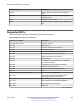
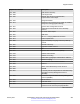

Table Of Contents
- Contents
- Chapter 1: Introduction
- Chapter 2: New in this document
- Chapter 3: Basic administration
- Chapter 4: System startup fundamentals
- Chapter 5: Boot parameter configuration using ACLI
- Chapter 6: Run-time process management using ACLI
- Chapter 7: Chassis operations
- Chassis operations fundamentals
- Chassis operations configuration using ACLI
- Enabling jumbo frames
- Configuring port lock
- Configuring SONMP
- Viewing the topology message status
- Associating a port to a VRF instance
- Configuring an IP address for the management port
- Configuring Ethernet ports with Autonegotiation
- Enabling channelization
- Configuring serial management port dropping
- Controlling slot power
- Enabling or disabling the USB port
- Chassis operations configuration using EDM
- Editing system information
- Editing chassis information
- Configuring system flags
- Configuring channelization
- Configuring basic port parameters
- Viewing the boot configuration
- Configuring boot flags
- Enabling Jumbo frames
- Configuring the date and time
- Associating a port to a VRF instance
- Configuring CP Limit
- Configuring an IP address for the management port
- Editing the management port parameters
- Configuring the management port IPv6 interface parameters
- Configuring management port IPv6 addresses
- Auto reactivating the port of the SLPP shutdown
- Editing serial port parameters
- Enabling port lock
- Locking a port
- Viewing power information
- Viewing power status on VSP 8400
- Viewing fan information
- Viewing topology status information
- Viewing the topology message status
- Configuring a forced message control pattern
- Chapter 8: Hardware status using EDM
- Chapter 9: Domain Name Service
- Chapter 10: Licensing
- Chapter 11: Network Time Protocol
- Chapter 12: Secure Shell
- Secure Shell fundamentals
- Secure Shell configuration using ACLI
- Downloading the software
- Enabling the SSHv2 server
- Changing the SSH server authentication mode
- Setting SSH configuration parameters
- Verifying and displaying SSH configuration information
- Connecting to a remote host using the SSH client
- Generating user key files
- Managing an SSL certificate
- Disabling SFTP without disabling SSH
- Enabling SSH rekey
- Configuring SSH rekey data-limit
- Configuring SSH rekey time-interval
- Displaying SSH rekey information
- Downgrading or upgrading from releases that support different key sizes
- Secure Shell configuration using Enterprise Device Manager
- Chapter 13: System access
- System access fundamentals
- System access configuration using ACLI
- Enabling ACLI access levels
- Changing passwords
- Configuring an access policy
- Specifying a name for an access policy
- Allowing a network access to the switch
- Configuring access policies by MAC address
- System access security enhancements
- Displaying the boot config flags status
- Enabling enhanced secure mode
- Creating accounts for different access levels
- Deleting accounts in enhanced secure mode
- Configuring a password for a specific user
- Returning the system to the factory defaults
- Configuring the password complexity rule
- Configuring the password length rule
- Configuring the change interval rule
- Configuring the reuse rule
- Configuring the maximum number of sessions
- Configuring the maximum age rule
- Configuring the pre- and post-notification rule
- System access configuration using EDM
- Chapter 14: ACLI show command reference
- Access, logon names, and passwords
- Basic switch configuration
- Current switch configuration
- CLI settings
- Ftp-access sessions
- Hardware information
- NTP server statistics
- Power summary
- Power information for power supplies
- System information
- System status (detailed)
- Telnet-access sessions
- Users logged on
- Port egress COS queue statistics
- CPU queue statistics
- Chapter 15: Port numbering and MAC address assignment reference
- Chapter 16: Supported standards, RFCs, and MIBs
- Glossary

3. QSFP+ port LEDs are in between the ports on each slot. The up arrows refer to the port above and the
down arrows refer to the port below.
4. Four QSFP+ ports: two in Slot 1 and two in Slot 2.
5. USB port
6. Console port (10101)
7. Management port — The LEDs are on the bottom of the port.
8. LEDs for system power (PWR), switch status (Status), redundant power supply (RPS), and fan
modules(Fan).
The following figure illustrates the front view of the VSP 8400 switch.
Figure 9: VSP 8404 front view
Looking at the front of the switch, slot numbering begins at the top row and increases from left to
right. Slot 1 is the top-left slot; slot 2 is the top-right slot. Slot 3 is the bottom-left slot; slot 4 is the
bottom-right slot.
Port numbering depends on the type of Ethernet Switch Module (ESM) installed in the slot. For more
information about ESMs, see Installing the Avaya Virtual Services Platform 8000 Series,
NN47227-300.
1. Displays the four slots to install ESMs.
2. LEDs for system power (PWR), switch status (Status), redundant power supply (RPS), and
fan modules (Fan).
3. USB port
4. Console port
5. OOB management port
The following figure illustrates the front view of the VSP 7200 switch.
When looking at the front of the switch:
• Slot 1 is the grouping of 48 ports.
• Slot 2 is the grouping of 6 40 Gbps ports to the right.
Port numbering
January 2017 Administering Avaya VSP 7200 Series and 8000 Series 233
Comments on this document? infodev@avaya.com