
Installation Instructions
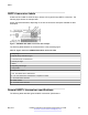


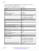


Table Of Contents
- Contents
- Chapter 1: Introduction
- Chapter 2: New in this document
- Chapter 3: Safety and equipment care information
- Chapter 4: Supported transceiver, BOCs, and DACs information
- Chapter 5: Optical routing design
- Chapter 6: SFP
- Chapter 7: SFP+
- SFP+ transceivers
- SFP+ specifications
- SFP+ labels
- General SFP+ specifications
- Supported SFP+ transceivers
- 10GBASE-T SFP+ transceiver
- 10GBASE-LR/LW SFP+ specifications
- 10GBASE-LR/LW SFP+ high temperature (-5 °C to +85 °C) specifications
- 10GBASE-ER/EW SFP+ specifications
- 10GBASE-SR/SW SFP+ specifications
- 10GBASE-SR/SW SFP+ high temperature (0 °C to +85 °C) specifications
- 10GBASE-ZR/ZW SFP+ specifications
- 10GBASE-CX specifications
- 10GBASE CWDM DDI SFP+ (40 km) specifications
- 10GBASE-LRM SFP+ specifications
- 10GBASE CWDM DDI SFP+ (70 km) specifications
- 10GBASE-BX SFP+ specifications
- Chapter 8: QSFP+
- Chapter 9: QSFP28
- Chapter 10: End of sale transceivers and cables
- Chapter 11: Translations of safety messages
- Class A electromagnetic interference warning statement
- Electrostatic discharge warning statement
- Laser eye safety danger statement
- Laser eye safety connector inspection danger statement
- Connector cleaning safety danger statement
- Optical fiber damage warning statement
- Optical fiber connector damage warning statement
- SFP damage warning statement
- Chapter 12: Resources
- Glossary

Parameter Specification
Applicable cable plant
Maximum insertion loss, including connectors 2.6 dB (OM3) or 2.9 dB (OM4)
Minimum optical return loss 20 dB
Maximum link distance 80 m
Receiver characteristics
Maximum average receive power, each lane 4.3 dBm
Maximum input optical power Tolerates direct Tx to Rx connection
Stressed receiver sensitivity –5.0 dBm
40GBASE-ER4 QSFP+ specifications
The following table lists the transmitter and receiver specifications for the 40GBASE-ER4 QSFP+
transceiver with corresponding wavelengths. The reach for this QSFP+ transceiver is up to 40
kilometers. The part number is AA1404003-E6.
40GBASE-ER4 QSFP+
The cable plant must have a minimum of 9 dB insertion loss between the transmitter and receiver
for correct operation. If the fiber cable does not have this much loss, use an attenuator to meet the 9
dB requirement. No attenuator is needed if insertion loss is at least 9 dB.
Table 36: IEEE 802.3ae 40GBASE-ER4 QSFP+ specifications
Parameter
Specification
Distance Up to 40 kilometers
Loss budget 18.5 dB
Transmitter characteristics
Line rate 10 Gbps
Signaling rate, each lane 10GBASE 10.3125 Gbps
Lane wavelength ranges 1264.5 nanometers to 1277.5 nanometers
1284.5 nanometers to 1297.5 nanometers
1304.5 nanometers to 1317.5 nanometers
1324.5 nanometers to 1337.5 nanometers
Total average optical power 10.5 dBm
Average optical power,
each lane at 10.3125
Gbps
Min.
–2.7
Max.
4.5
Units
dBm
Difference in optical power between any two lanes 4.7 dB OMA
Minimum side mode suppression ratio 30 dBm
Optical modulation
amplitude
Min.
0.3
Max.
5
Units
dBm
QSFP+
May 2017 Installing Transceivers and Optical Components on VOSS 68
Comments on this document? infodev@avaya.com