
Installation Instructions


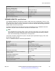


Table Of Contents
- Contents
- Chapter 1: Introduction
- Chapter 2: New in this document
- Chapter 3: Safety and equipment care information
- Chapter 4: Supported transceiver, BOCs, and DACs information
- Chapter 5: Optical routing design
- Chapter 6: SFP
- Chapter 7: SFP+
- SFP+ transceivers
- SFP+ specifications
- SFP+ labels
- General SFP+ specifications
- Supported SFP+ transceivers
- 10GBASE-T SFP+ transceiver
- 10GBASE-LR/LW SFP+ specifications
- 10GBASE-LR/LW SFP+ high temperature (-5 °C to +85 °C) specifications
- 10GBASE-ER/EW SFP+ specifications
- 10GBASE-SR/SW SFP+ specifications
- 10GBASE-SR/SW SFP+ high temperature (0 °C to +85 °C) specifications
- 10GBASE-ZR/ZW SFP+ specifications
- 10GBASE-CX specifications
- 10GBASE CWDM DDI SFP+ (40 km) specifications
- 10GBASE-LRM SFP+ specifications
- 10GBASE CWDM DDI SFP+ (70 km) specifications
- 10GBASE-BX SFP+ specifications
- Chapter 8: QSFP+
- Chapter 9: QSFP28
- Chapter 10: End of sale transceivers and cables
- Chapter 11: Translations of safety messages
- Class A electromagnetic interference warning statement
- Electrostatic discharge warning statement
- Laser eye safety danger statement
- Laser eye safety connector inspection danger statement
- Connector cleaning safety danger statement
- Optical fiber damage warning statement
- Optical fiber connector damage warning statement
- SFP damage warning statement
- Chapter 12: Resources
- Glossary

Parameter Specifications
Minimum extinction ratio 3.5 dB
Optical return loss tolerance (minimum) –20 dB
Receiver characteristics
Receiver damage threshold 1.5 dBm
Receiver reflectance (maximum) –12 dB
For more information about the conditions used for the stressed receiver tests, and other
information, see the IEEE 802.3–2012 standard.
The following table (from IEEE 802.3–2012) describes the maximum channel insertion loss. The
channel insertion loss includes both attenuation and connector loss (1.5 dB); therefore the maximum
fiber attenuation is 0.2 to 0.4 dB.
Table 28: 10GBASE-LRM channel insertion loss and range
Fiber type (core diameter and OFL bandwidth) Range Maximum channel
insertion loss
62.5 μm (FDDI grade)
• 160 MHz-km at 850 nm
• 500 MHz-km at 1300 nm
Up to 220 m 1.9 dB
62.5 μm (ISO/IEC OM1)
• 200 MHz-km at 850 nm
• 500 MHz-km at 1300 nm
Up to 220 m 1.9 dB
50 μm (ISO/IEC OM2)
• 500 MHz-km at 850 nm
• 500 MHz-km at 1300 nm
Up to 220 m 1.9 dB
50 μm
• 400 MHz-km at 850 nm
• 400 MHz-km at 1300 nm
Up to 100 m 1.7 dB
50 μm (ISO/IEC OM3)
• 1500 MHz-km at 850 nm (includes laser launch
bandwidth)
• 500 MHz-km at 1300 nm (includes laser launch
bandwidth)
Up to 220 m 1.9 dB
The following abbreviations are used in the preceding tables:
• FDDI – Fiber Distributed Data Interface
• ISO – International Standards Organization
• IEC – International Electrotechnical Commission
• OFL – Over Filled Launch
SFP+
May 2017 Installing Transceivers and Optical Components on VOSS 54
Comments on this document? infodev@avaya.com