
Installation Instructions

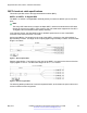


Table Of Contents
- Contents
- Chapter 1: Introduction
- Chapter 2: New in this document
- Chapter 3: Safety and equipment care information
- Chapter 4: Supported transceiver, BOCs, and DACs information
- Chapter 5: Optical routing design
- Chapter 6: SFP
- Chapter 7: SFP+
- SFP+ transceivers
- SFP+ specifications
- SFP+ labels
- General SFP+ specifications
- Supported SFP+ transceivers
- 10GBASE-T SFP+ transceiver
- 10GBASE-LR/LW SFP+ specifications
- 10GBASE-LR/LW SFP+ high temperature (-5 °C to +85 °C) specifications
- 10GBASE-ER/EW SFP+ specifications
- 10GBASE-SR/SW SFP+ specifications
- 10GBASE-SR/SW SFP+ high temperature (0 °C to +85 °C) specifications
- 10GBASE-ZR/ZW SFP+ specifications
- 10GBASE-CX specifications
- 10GBASE CWDM DDI SFP+ (40 km) specifications
- 10GBASE-LRM SFP+ specifications
- 10GBASE CWDM DDI SFP+ (70 km) specifications
- 10GBASE-BX SFP+ specifications
- Chapter 8: QSFP+
- Chapter 9: QSFP28
- Chapter 10: End of sale transceivers and cables
- Chapter 11: Translations of safety messages
- Class A electromagnetic interference warning statement
- Electrostatic discharge warning statement
- Laser eye safety danger statement
- Laser eye safety connector inspection danger statement
- Connector cleaning safety danger statement
- Optical fiber damage warning statement
- Optical fiber connector damage warning statement
- SFP damage warning statement
- Chapter 12: Resources
- Glossary

QSFP+ breakout cable specifications
This section provides a list of the supported breakout cables (BOC).
QSFP+ to 4xSFP+ 10 Gigabit BOC
The QSFP+ to 4xSFP+ 10 Gigabit BOC assembly directly connects one QSFP+ port to four SFP+
ports.
Note:
The Avaya VSP 4000 does not support 40 Gbps QSFP+ transceivers because the VSP 4000
devices do not have any QSFP+ ports. However, the VSP 4000 series supports the four SFP+
10 Gigabit ends of the breakout cable (BOC) assembly.
In the following figures, the total cable length for all BOCs spans from the nose of the QSFP+
connector to the nose of the SFP+ connector.
Active optical BOCs—The length from the nose of the QSFP+ connector to the optical splitter is
approximately 8 meters. The length of each optical pigtail is approximately 2 meters. The total cable
length is 10 meters.
Figure 1: Active optical BOC
Passive copper BOCs—The length from the nose of the QSFP+ connector to the fanout of the four
copper pigtails is 10.2 cm. The total cable length can be 1, 3, or 5 meters.
Figure 2: Passive copper BOC
The following tables provide a list of active and passive BOCs, and includes the part numbers and
minimum software version supported.
Supported transceiver, BOCs, and DACs information
May 2017 Installing Transceivers and Optical Components on VOSS 22
Comments on this document? infodev@avaya.com