
Installation Instructions


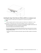


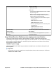

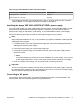
Table Of Contents
- Installation Job Aid (English) for Avaya VSP 4000 4450GTX-HT-PWR+
- How to get help
- Notices
- Safety messages
- Location restrictions
- Before you begin
- Installing the VSP 4000 4450GTX-HT-PWR+
- Installing the Avaya Virtual Services Platform 4000 on a table or shelf
- Installing the Avaya Virtual Services Platform 4000 in an equipment rack
- Installing SFP transceivers
- Removing SFP transceivers
- Power specifications for Avaya VSP 4000 switch 4450GTX-HT-PWR+
- Avaya Virtual Services Platform power supply power specification
- Installing the Avaya VSP 4000 4450GTX-HT-PWR+ power supply
- Connecting to AC power

Installing the Avaya Virtual Services Platform 4000 in an equipment rack
To install an Avaya VSP 4000 switch in an equipment rack, perform this procedure.
Note:
A factory-supplied 4450GTX-HT-PWR+ switch has a USB slot but no USB device or cover.
Prerequisites for installing the Avaya Virtual Services Platform 4000 in an equipment rack:
• Ensure that you have a space of 1.75 inches (4.45 centimeters) in height for each switch in an
EIA or IEC-standard 19-inch (48.2-centimeter) equipment rack.
• The rack is bolted to the floor and braced if necessary.
• The rack is grounded to the same grounding electrode used by the power service in the area.
The ground path must be permanent and must not exceed 1 Ohm of resistance from the rack
to the grounding electrode.
1. Attach the L-bracket to each side of the switch using a #2 Phillips screwdriver as illustrated
below.
August 2014 Installation Job Aid (English) for Avaya VSP 4000 4450GTX-HT-PWR+ 5