
Installation Instructions


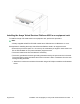


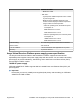

Table Of Contents
- Installation Job Aid (English) for Avaya VSP 4000 4450GTX-HT-PWR+
- How to get help
- Notices
- Safety messages
- Location restrictions
- Before you begin
- Installing the VSP 4000 4450GTX-HT-PWR+
- Installing the Avaya Virtual Services Platform 4000 on a table or shelf
- Installing the Avaya Virtual Services Platform 4000 in an equipment rack
- Installing SFP transceivers
- Removing SFP transceivers
- Power specifications for Avaya VSP 4000 switch 4450GTX-HT-PWR+
- Avaya Virtual Services Platform power supply power specification
- Installing the Avaya VSP 4000 4450GTX-HT-PWR+ power supply
- Connecting to AC power

Table 4: Avaya VSP 4450GTX-HT-PWR+ model with 2 PSUs
0°C to 50°C 50°C to 70°C
PoE support on 48 ports 48 ports
PoE+ support on 48 ports 26 ports
• VSP 4450GTX-HT-PWR+ can support 802.3af 17.8W or 32.4W on each port with one power
supply installed. You can add a second power supply for redundancy.
Installing the Avaya VSP 4000 4450GTX-HT-PWR+ power supply
You must install at least one power supply before using the switch. Avaya VSP 4000 PWR+ models
support two field replaceable external power supplies. If supported, you can install an optional
second power supply for redundancy, load sharing, or to provide additional PoE+ power budget.
Perform the following procedure to install an external power supply into your switch.
Note:
Avaya VSP 4000 hardware can vary. This procedure only applies to hardware models with field
replaceable power supplies.
1. If a blanking plate covers the required power supply slot, remove the blanking plate before
attempting to insert the power supply.
2. Insert each power supply into a front power supply slot.
3. Verify that each power supply is fully seated in the slot. Secure the power supply with the
two thumb screws.
Note:
The switch chassis can prevent an incorrect installation of a power supply. If you insert a
power supply upside down, it will not fully insert and the thumb screws will not engage.
4. Once you install a power supply, you can proceed with connecting AC power.
Important:
You can hot swap power supplies while the switch is operational. One power supply is required
for continued switch operation. PoE+ load reductions can occur if you remove one power supply
while the switch is operating with dual power supplies.
Connecting to AC power
To connect AC power to the switch, you need an appropriate AC power cord as described in the
following table, also see the following table for plug specifications.
August 2014 Installation Job Aid (English) for Avaya VSP 4000 4450GTX-HT-PWR+ 10