
Installation Instructions
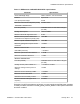


Table Of Contents
- Contents
- Chapter 1: Avaya Virtual Services Platform 4000 regulatory information and safety precautions
- International regulatory statements of conformity
- National electromagnetic compliance (EMC) statements of compliance
- FCC statement (USA only)
- ICES statement (Canada only)
- CE marking statement (Europe only)
- European Union and European Free Trade Association (EFTA) notice
- VCCI statement (Japan/Nippon only)
- BSMI statement (Taiwan only)
- MIC notice (Republic of Korea only)
- National Safety Statements of Compliance
- EN 60950 statement
- NOM statement (Mexico only)
- Información NOM (unicamente para México)
- Denan statement (Japan/Nippon only)
- National Environmental Statements of Compliance
- Restriction on Hazardous Substances Directive Compliance Statement
- WEEE Directive Compliance Statement
- Chapter 2: Introduction
- Chapter 3: New in this release
- Chapter 4: Safety and equipment care information
- Chapter 5: Small form factor pluggable transceivers
- Chapter 6: Small form factor pluggable plus transceivers
- Chapter 7: SFP specifications
- SFP labels
- General SFP specifications
- 1000BASE-T (RJ-45) SFP specifications
- 1000BASE-SX (LC) DDI SFP specifications
- 1000BASE-LX (LC) DDI SFP specifications
- 1000BASE-XD DDI 1310 nm SFP specifications
- 1000BASE-XD DDI 1550 nm SFP specifications
- 1000BASE-ZX DDI SFP specifications
- 1000BASE-XD CWDM (LC) SFP specifications
- 1000BASE-ZX CWDM (LC) SFP specifications
- 1000BASE-BX10 DDI SFP specifications
- 1000BASE-EX DDI SFP specifications
- 1000BASE-BX40 bidirectional SFP specifications
- 100BASE-FX SFP specifications
- Chapter 8: SFP+ specifications

Fiber type (core diameter and OFL
bandwidth)
Range Maximum
channel insertion
loss
• 1500 MHz-km at 850 nm (includes laser
launch bandwidth)
• 500 MHz-km at 1300 nm (includes laser
launch bandwidth)
In the table, FDDI denotes Fiber Distributed Data Interface, ISO denotes International
Standards Organization, IEC denotes International Electrotechnical Commission, and OFL
denotes Over Filled Launch.
The following table uses the 802.3aq standard and specifies the measurement conditions for
each fiber type.
Table 25: Launch conditions for each fiber type
Parameter Minimum encircled flux Notes
Optical launch for OM1 and
FDDI-grade fiber
• 30% within 5 μm radius
• 81% within 11 μm radius
Uses 62.5 μmmode
conditioning patch cord
Optical launch for OM2 and
50 μm 400/400 fiber
• 30% within 5 μm radius
• 81% within 11 μm radius
Uses 50 μmmode
conditioning patch cord
Optical launch for OM3 and
50 μm fiber
• 30% within 5 μm radius
• 81% within 11 μm radius
—
10GBASE-CX specifications
The 10GBASE-CX is a 4-pair twinaxial copper cable that plugs into the SFP+ socket and
connects two 10 Gb ports. The reach for this cable is up to 15 m with a bit error rate (BER)
better than 10
-12
. The signaling speed for each lane is 3.125 GBd ± 100 ppm. The 10GBASE-
CX is a lower cost alternative to the optical SFP+ devices.
For more information about the 10GBASE-CX, including test and measurement information
and more specifications, see the IEEE 802.3ak standard. The following table identifies the part
numbers for specific cable lengths.
Table 26: 10GBASE-CX cables
Cable length
Part number
3 meter AA1403019-E6
10GBASE-CX specifications
Installation — SFP and SFP+ transceivers January 2014 65