
Installation Instructions
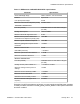


Table Of Contents
- Contents
- Chapter 1: Avaya Virtual Services Platform 4000 regulatory information and safety precautions
- International regulatory statements of conformity
- National electromagnetic compliance (EMC) statements of compliance
- FCC statement (USA only)
- ICES statement (Canada only)
- CE marking statement (Europe only)
- European Union and European Free Trade Association (EFTA) notice
- VCCI statement (Japan/Nippon only)
- BSMI statement (Taiwan only)
- MIC notice (Republic of Korea only)
- National Safety Statements of Compliance
- EN 60950 statement
- NOM statement (Mexico only)
- Información NOM (unicamente para México)
- Denan statement (Japan/Nippon only)
- National Environmental Statements of Compliance
- Restriction on Hazardous Substances Directive Compliance Statement
- WEEE Directive Compliance Statement
- Chapter 2: Introduction
- Chapter 3: New in this release
- Chapter 4: Safety and equipment care information
- Chapter 5: Small form factor pluggable transceivers
- Chapter 6: Small form factor pluggable plus transceivers
- Chapter 7: SFP specifications
- SFP labels
- General SFP specifications
- 1000BASE-T (RJ-45) SFP specifications
- 1000BASE-SX (LC) DDI SFP specifications
- 1000BASE-LX (LC) DDI SFP specifications
- 1000BASE-XD DDI 1310 nm SFP specifications
- 1000BASE-XD DDI 1550 nm SFP specifications
- 1000BASE-ZX DDI SFP specifications
- 1000BASE-XD CWDM (LC) SFP specifications
- 1000BASE-ZX CWDM (LC) SFP specifications
- 1000BASE-BX10 DDI SFP specifications
- 1000BASE-EX DDI SFP specifications
- 1000BASE-BX40 bidirectional SFP specifications
- 100BASE-FX SFP specifications
- Chapter 8: SFP+ specifications

Parameter Specifications
Launch power in OMA – 4.5 to 1.5 dBm
Maximum average launch power of OFF
transmitter
– 30 dBm
Minimum extinction ratio 3.5 dB
Maximum relative intensity noise at OMA—
RIN
12
OMA
– 128 dB/Hz
Optical return loss tolerance (minimum) – 20 dB
Receiver characteristics
Maximum receive average power for
damage
1.5 dBm
Receiver reflectance (maximum) – 12 dB
For more information about the conditions used for the stressed receiver tests, and other
information, see the IEEE 802.3aq standard.
The following table (from IEEE 802.3aq) describes the maximum channel insertion loss. The
channel insertion loss includes both attenuation and connector loss (1.5 dB); therefore the
maximum fiber attenuation is 0.2 to 0.4 dB.
Table 24: 10GBASE-LRM channel insertion loss and range
Fiber type (core diameter and OFL
bandwidth)
Range Maximum
channel insertion
loss
62.5 μm (FDDI grade)
• 160 MHz-km at 850 nm
• 500 MHz-km at 1300 nm
Up to 220 m 1.9 dB
62.5 μm (ISO/IEC OM1)
• 200 MHz-km at 850 nm
• 500 MHz-km at 1300 nm
Up to 220 m 1.9 dB
50 μm (ISO/IEC OM2)
• 500 MHz-km at 850 nm
• 500 MHz-km at 1300 nm
Up to 220 m 1.9 dB
50 μm
• 400 MHz-km at 850 nm
• 400 MHz-km at 1300 nm
Up to 100 m 1.7 dB
50 μm (ISO/IEC OM3) Up to 220 m 1.9 dB
SFP+ specifications
64 Installation — SFP and SFP+ transceivers January 2014
Comments? infodev@avaya.com