
Installation Instructions

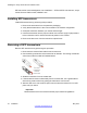


Table Of Contents
- Contents
- Chapter 1: Avaya Virtual Services Platform 4000 regulatory information and safety precautions
- International regulatory statements of conformity
- National electromagnetic compliance (EMC) statements of compliance
- FCC statement (USA only)
- ICES statement (Canada only)
- CE marking statement (Europe only)
- European Union and European Free Trade Association (EFTA) notice
- VCCI statement (Japan/Nippon only)
- BSMI statement (Taiwan only)
- MIC notice (Republic of Korea only)
- National Safety Statements of Compliance
- EN 60950 statement
- NOM statement (Mexico only)
- Información NOM (unicamente para México)
- Denan statement (Japan/Nippon only)
- National Environmental Statements of Compliance
- Restriction on Hazardous Substances Directive Compliance Statement
- WEEE Directive Compliance Statement
- Chapter 2: Introduction
- Chapter 3: New in this release
- Chapter 4: Hardware compatibility
- Chapter 5: Installing the Avaya Virtual Services Platform 4000
- Installation fundamentals
- Electrostatic discharge
- Environmental requirements
- Package contents
- Installing the Avaya Virtual Services Platform 4000 on a table or shelf
- Installing the Avaya Virtual Services Platform 4000 in an equipment rack
- Cable requirements for the Avaya Virtual Services Platform 4000
- Installation and removal of Small Form-factor Pluggable (SFP) transceivers
- RJ-45 connector pin assignments
- Console port pin assignments
- Power specifications for the Avaya Virtual Services Platform 4000
- Avaya Virtual Services Platform power supply power specification
- Installing the Avaya Virtual Services Platform 4000 power supply
- Connect AC power
- Check Light Emitting Diode (LED) on the Avaya Virtual Services Platform 4000
- Chapter 6: Translations of safety messages

SFP transceiver use and designation, see Installation — SFP and SFP+ transceivers, Avaya
Virtual Services Platform 4000, NN46251–301
.
Installing SFP transceivers
Install SFP transceivers by performing this procedure.
1.
Remove the transceiver from the protective packaging.
2. Verify that the transceiver is the correct model for the network configuration.
3. Grasp the transceiver between your thumb and forefinger.
4. Insert the transceiver into the proper module on the switch. Apply a light pressure
to the transceiver until it clicks and locks into position in the module.
5. Remove the dust cover from the transceiver optical bores.
Removing of SFP transceivers
Remove SFP transceivers by performing this procedure.
1.
Disconnect the network fiber cable from the transceiver.
2. Use the locking mechanism on the transceiver to release it. The locking mechanism
varies from model to model as illustrated below.
3. Slide the transceiver from the module slot.
4.
If the transceiver does not slide easily from the module slot, use a gentle side-to-
side rocking motion while firmly pulling the transceiver from the slot.
5. Attach a dust cover over the fiber-optic bores and store the transceiver in a safe
place until you need it.
Important:
Discard transceivers in accordance with the proper laws and regulations.
Installing the Avaya Virtual Services Platform 4000
32 Installation May 2013
Comments? infodev@avaya.com