
Installation Instructions


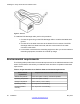


Table Of Contents
- Contents
- Chapter 1: Avaya Virtual Services Platform 4000 regulatory information and safety precautions
- International regulatory statements of conformity
- National electromagnetic compliance (EMC) statements of compliance
- FCC statement (USA only)
- ICES statement (Canada only)
- CE marking statement (Europe only)
- European Union and European Free Trade Association (EFTA) notice
- VCCI statement (Japan/Nippon only)
- BSMI statement (Taiwan only)
- MIC notice (Republic of Korea only)
- National Safety Statements of Compliance
- EN 60950 statement
- NOM statement (Mexico only)
- Información NOM (unicamente para México)
- Denan statement (Japan/Nippon only)
- National Environmental Statements of Compliance
- Restriction on Hazardous Substances Directive Compliance Statement
- WEEE Directive Compliance Statement
- Chapter 2: Introduction
- Chapter 3: New in this release
- Chapter 4: Hardware compatibility
- Chapter 5: Installing the Avaya Virtual Services Platform 4000
- Installation fundamentals
- Electrostatic discharge
- Environmental requirements
- Package contents
- Installing the Avaya Virtual Services Platform 4000 on a table or shelf
- Installing the Avaya Virtual Services Platform 4000 in an equipment rack
- Cable requirements for the Avaya Virtual Services Platform 4000
- Installation and removal of Small Form-factor Pluggable (SFP) transceivers
- RJ-45 connector pin assignments
- Console port pin assignments
- Power specifications for the Avaya Virtual Services Platform 4000
- Avaya Virtual Services Platform power supply power specification
- Installing the Avaya Virtual Services Platform 4000 power supply
- Connect AC power
- Check Light Emitting Diode (LED) on the Avaya Virtual Services Platform 4000
- Chapter 6: Translations of safety messages

Prerequisites for installing the Avaya Virtual Services Platform 4000 in an equipment rack:
• Ensure that you have a space of 1.75 inches (4.45 centimeters) in height for each switch
in an EIA or IEC-standard 19-inch (48.2-centimeter) equipment rack.
• The rack is bolted to the floor and braced if necessary.
• The rack is grounded to the same grounding electrode used by the power service in the
area. The ground path must be permanent and must not exceed 1 Ohm of resistance
from the rack to the grounding electrode.
Caution:
When
you mount the device in a rack, do not stack units directly on top of one another. You
must secure each unit to the rack with the appropriate mounting brackets. Mounting brackets
cannot support multiple units. For a translation of this statement, see
Translations of safety
messages on page 45.
1.
Remove the screws that hold the USB cover, but do not remove the USB cover.
2. Attach a bracket to each side of the switch using a #2 Phillips screwdriver as
illustrated below. The bracket goes over the USB cover.
3. Slide the switch into the rack as illustrated.
4. Insert and tighten the rack-mount screws.
Installing the Avaya Virtual Services Platform 4000
30 Installation May 2013
Comments? infodev@avaya.com