
Installation Instructions


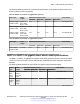

Table Of Contents
- Contents
- Chapter 1: Introduction
- Chapter 2: New in this document
- Chapter 3: Optical routing design
- Chapter 4: Safety and equipment care information
- Chapter 5: SFP
- SFP transceivers
- SFP specifications
- SFP labels
- General SFP specifications
- Supported SFP transceivers
- Autonegotiation
- 1000BASE-SX (LC) SFP specifications
- 1000BASE-SX (MT-RJ) SFP specifications
- 1000BASE-LX SFP specifications
- 1000BASE-XD CWDM SFP specifications
- 1000BASE-ZX CWDM (LC) SFP specifications
- 1000BASE-T SFP specifications
- 1000BASE-SX DDI SFP specifications
- 1000BASE-LX DDI SFP specifications
- 1000BASE-XD DDI 1310 nm SFP specifications
- 1000BASE-XD DDI 1550 nm SFP specifications
- 1000BASE-ZX DDI 1550 nm SFP specifications
- 1000BASE-XD DDI CWDM (40 km) SFP specifications
- 1000BASE-ZX DDI CWDM 70 km SFP specifications
- 1000BASE-BX bidirectional SFP transceivers
- 1000BASE-EX DDI SFP specifications
- 100BASE-FX SFP specifications
- Chapter 6: SFP+
- SFP+ transceivers
- SFP+ specifications
- SFP+ labels
- General SFP+ specifications
- Supported SFP+ transceivers
- 10GBASE-T SFP+ transceiver
- 10GBASE-LR/LW SFP+ specifications
- 10GBASE-LR/LW SFP+ high temperature (-5 °C to +85 °C) specifications
- 10GBASE-ER/EW SFP+ specifications
- 10GBASE-SR/SW SFP+ specifications
- 10GBASE-SR/SW SFP+ high temperature (0 °C to +85 °C) specifications
- 10GBASE-ZR/ZW SFP+ specifications
- 10GBASE-CX specifications
- 10GBASE CWDM DDI SFP+ (40 km) specifications
- 10GBASE-LRM SFP+ specifications
- 10GBASE CWDM DDI SFP+ (70 km) specifications
- 10GBASE-BX SFP+ specifications
- SFP+ cable assembly specifications
- Chapter 7: QSFP+
- Chapter 8: Translations of safety messages
- Class A electromagnetic interference warning statement
- Electrostatic discharge warning statement
- Laser eye safety danger statement
- Laser eye safety connector inspection danger statement
- Connector cleaning safety danger statement
- Optical fiber damage warning statement
- Optical fiber connector damage warning statement
- SFP damage warning statement
- Glossary

QSFP+ transceiver specifications
This section provides technical specifications for the supported 40 gigabit QSFP+ transceiver
models. Use these specifications to aid in network design.
Important:
The VSP switches operate in strict mode for QSFP+ transceivers, which means that the switch
will not bring the port up operationally when using non-Avaya QSFP+ transceivers.
QSFP+ transceiver labels
A label can be located on either the top or bottom of the typical Avaya QSFP+ transceiver. The
following figure shows an example label.
Avaya uses alternate labels, depending on the size of the device and space available for label
information.
Figure 5: 40GBASE–SR4 QSFP+ transceiver label example
The following table identifies the numbered items in the preceding figure.
Table 38: Figure notes for a 40GBASE–SR4 QSFP+ transceiver label
1. Avaya logo
2. Optical safety certification logos
3. Year and month of manufacture
4. Country of origin
5. Name
6. Operating wavelength
7. Avaya PEC
8. Vendor part number
9. U.S. FDA CDRH laser classification
10. U.S. FDA CDRH laser classification compliance number
11. 2D serial number barcode
Table continues…
QSFP+ transceiver specifications
December 2016 Installing Transceivers and Optical Components on Avaya VSP Operating System
Software 71
Comments on this document? infodev@avaya.com