
Installation Instructions
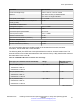


Table Of Contents
- Contents
- Chapter 1: Introduction
- Chapter 2: New in this document
- Chapter 3: Optical routing design
- Chapter 4: Safety and equipment care information
- Chapter 5: SFP
- SFP transceivers
- SFP specifications
- SFP labels
- General SFP specifications
- Supported SFP transceivers
- Autonegotiation
- 1000BASE-SX (LC) SFP specifications
- 1000BASE-SX (MT-RJ) SFP specifications
- 1000BASE-LX SFP specifications
- 1000BASE-XD CWDM SFP specifications
- 1000BASE-ZX CWDM (LC) SFP specifications
- 1000BASE-T SFP specifications
- 1000BASE-SX DDI SFP specifications
- 1000BASE-LX DDI SFP specifications
- 1000BASE-XD DDI 1310 nm SFP specifications
- 1000BASE-XD DDI 1550 nm SFP specifications
- 1000BASE-ZX DDI 1550 nm SFP specifications
- 1000BASE-XD DDI CWDM (40 km) SFP specifications
- 1000BASE-ZX DDI CWDM 70 km SFP specifications
- 1000BASE-BX bidirectional SFP transceivers
- 1000BASE-EX DDI SFP specifications
- 100BASE-FX SFP specifications
- Chapter 6: SFP+
- SFP+ transceivers
- SFP+ specifications
- SFP+ labels
- General SFP+ specifications
- Supported SFP+ transceivers
- 10GBASE-T SFP+ transceiver
- 10GBASE-LR/LW SFP+ specifications
- 10GBASE-LR/LW SFP+ high temperature (-5 °C to +85 °C) specifications
- 10GBASE-ER/EW SFP+ specifications
- 10GBASE-SR/SW SFP+ specifications
- 10GBASE-SR/SW SFP+ high temperature (0 °C to +85 °C) specifications
- 10GBASE-ZR/ZW SFP+ specifications
- 10GBASE-CX specifications
- 10GBASE CWDM DDI SFP+ (40 km) specifications
- 10GBASE-LRM SFP+ specifications
- 10GBASE CWDM DDI SFP+ (70 km) specifications
- 10GBASE-BX SFP+ specifications
- SFP+ cable assembly specifications
- Chapter 7: QSFP+
- Chapter 8: Translations of safety messages
- Class A electromagnetic interference warning statement
- Electrostatic discharge warning statement
- Laser eye safety danger statement
- Laser eye safety connector inspection danger statement
- Connector cleaning safety danger statement
- Optical fiber damage warning statement
- Optical fiber connector damage warning statement
- SFP damage warning statement
- Glossary

Fiber type (core diameter and OFL bandwidth) Range Maximum channel
insertion loss
50 μm
• 400 MHz-km at 850 nm
• 400 MHz-km at 1300 nm
Up to 100 m 1.7 dB
50 μm (ISO/IEC OM3)
• 1500 MHz-km at 850 nm (includes laser launch
bandwidth)
• 500 MHz-km at 1300 nm (includes laser launch
bandwidth)
Up to 220 m 1.9 dB
The following abbreviations are used in the preceding tables:
• FDDI – Fiber Distributed Data Interface
• ISO – International Standards Organization
• IEC – International Electrotechnical Commission
• OFL – Over Filled Launch
10GBASE CWDM DDI SFP+ (70 km) specifications
The following table lists the part numbers for the 10GBASE CWDM DDI SFP+ (70 km) transceivers
with corresponding wavelengths.
The reach for this SFP+ transceiver is up to 70 km* at a wavelength of 1551 nm.
Table 35: Part number and center wavelength assignment
Part number Center wavelength
assignment
Reach Minimum insertion loss
Tx and Rx
AA1403161-E6 1471 nm 70 km 10 dB
AA1403162-E6 1491 nm 70 km 10 dB
AA1403163-E6 1511 nm 70 km 10 dB
AA1403164-E6 1531 nm 70 km 10 dB
AA1403165-E6 1551 nm 70 km 10 dB
AA1403166-E6 1571 nm 70 km 10 dB
AA1403167-E6 1591 nm 70 km 10 dB
AA1403168-E6 1611 nm 70 km 10 dB
* Achievable link distance is primarily dependent on cable plant insertion loss. 70 km is not possible
in some situations.
The following table lists the transmitter and receiver specifications for the 10GBASE CWDM DDI
SFP+ (70 km) transceiver.
SFP+
December 2016 Installing Transceivers and Optical Components on Avaya VSP Operating System
Software 62
Comments on this document? infodev@avaya.com