
Installation Instructions
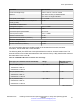


Table Of Contents
- Contents
- Chapter 1: Introduction
- Chapter 2: New in this document
- Chapter 3: Optical routing design
- Chapter 4: Safety and equipment care information
- Chapter 5: SFP
- SFP transceivers
- SFP specifications
- SFP labels
- General SFP specifications
- Supported SFP transceivers
- Autonegotiation
- 1000BASE-SX (LC) SFP specifications
- 1000BASE-SX (MT-RJ) SFP specifications
- 1000BASE-LX SFP specifications
- 1000BASE-XD CWDM SFP specifications
- 1000BASE-ZX CWDM (LC) SFP specifications
- 1000BASE-T SFP specifications
- 1000BASE-SX DDI SFP specifications
- 1000BASE-LX DDI SFP specifications
- 1000BASE-XD DDI 1310 nm SFP specifications
- 1000BASE-XD DDI 1550 nm SFP specifications
- 1000BASE-ZX DDI 1550 nm SFP specifications
- 1000BASE-XD DDI CWDM (40 km) SFP specifications
- 1000BASE-ZX DDI CWDM 70 km SFP specifications
- 1000BASE-BX bidirectional SFP transceivers
- 1000BASE-EX DDI SFP specifications
- 100BASE-FX SFP specifications
- Chapter 6: SFP+
- SFP+ transceivers
- SFP+ specifications
- SFP+ labels
- General SFP+ specifications
- Supported SFP+ transceivers
- 10GBASE-T SFP+ transceiver
- 10GBASE-LR/LW SFP+ specifications
- 10GBASE-LR/LW SFP+ high temperature (-5 °C to +85 °C) specifications
- 10GBASE-ER/EW SFP+ specifications
- 10GBASE-SR/SW SFP+ specifications
- 10GBASE-SR/SW SFP+ high temperature (0 °C to +85 °C) specifications
- 10GBASE-ZR/ZW SFP+ specifications
- 10GBASE-CX specifications
- 10GBASE CWDM DDI SFP+ (40 km) specifications
- 10GBASE-LRM SFP+ specifications
- 10GBASE CWDM DDI SFP+ (70 km) specifications
- 10GBASE-BX SFP+ specifications
- SFP+ cable assembly specifications
- Chapter 7: QSFP+
- Chapter 8: Translations of safety messages
- Class A electromagnetic interference warning statement
- Electrostatic discharge warning statement
- Laser eye safety danger statement
- Laser eye safety connector inspection danger statement
- Connector cleaning safety danger statement
- Optical fiber damage warning statement
- Optical fiber connector damage warning statement
- SFP damage warning statement
- Glossary

Parameter Specifications
Center wavelength range 1260 to 1355 nm; 1310 nm nominal
Distance Up to 220 m on 62.5 µm multimode fiber
Up to 300 m on single mode fiber
Link optical power budget 1.7 to 1.9 dB
Maximum transmitter waveform and dispersion
penalty (TWDP)
4.7 dB
Transmitter characteristics
Average launch power –6.5 to 0.5 dBm
Peak launch power 3 dBm
Root-mean-square spectral width 2.4 to 4 nm
Launch power in OMA –4.5 to 1.5 dBm
Minimum extinction ratio 3.5 dB
Optical return loss tolerance (minimum) –20 dB
Receiver characteristics
Receiver damage threshold 1.5 dBm
Receiver reflectance (maximum) –12 dB
For more information about the conditions used for the stressed receiver tests, and other
information, see the IEEE 802.3–2012 standard.
The following table (from IEEE 802.3–2012) describes the maximum channel insertion loss. The
channel insertion loss includes both attenuation and connector loss (1.5 dB); therefore the maximum
fiber attenuation is 0.2 to 0.4 dB.
Table 34: 10GBASE-LRM channel insertion loss and range
Fiber type (core diameter and OFL bandwidth) Range Maximum channel
insertion loss
62.5 μm (FDDI grade)
• 160 MHz-km at 850 nm
• 500 MHz-km at 1300 nm
Up to 220 m 1.9 dB
62.5 μm (ISO/IEC OM1)
• 200 MHz-km at 850 nm
• 500 MHz-km at 1300 nm
Up to 220 m 1.9 dB
50 μm (ISO/IEC OM2)
• 500 MHz-km at 850 nm
• 500 MHz-km at 1300 nm
Up to 220 m 1.9 dB
Table continues…
SFP+ specifications
December 2016 Installing Transceivers and Optical Components on Avaya VSP Operating System
Software 61
Comments on this document? infodev@avaya.com