
Installation Instructions


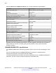

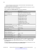
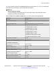


Table Of Contents
- Contents
- Chapter 1: Introduction
- Chapter 2: New in this document
- Chapter 3: Optical routing design
- Chapter 4: Safety and equipment care information
- Chapter 5: SFP
- SFP transceivers
- SFP specifications
- SFP labels
- General SFP specifications
- Supported SFP transceivers
- Autonegotiation
- 1000BASE-SX (LC) SFP specifications
- 1000BASE-SX (MT-RJ) SFP specifications
- 1000BASE-LX SFP specifications
- 1000BASE-XD CWDM SFP specifications
- 1000BASE-ZX CWDM (LC) SFP specifications
- 1000BASE-T SFP specifications
- 1000BASE-SX DDI SFP specifications
- 1000BASE-LX DDI SFP specifications
- 1000BASE-XD DDI 1310 nm SFP specifications
- 1000BASE-XD DDI 1550 nm SFP specifications
- 1000BASE-ZX DDI 1550 nm SFP specifications
- 1000BASE-XD DDI CWDM (40 km) SFP specifications
- 1000BASE-ZX DDI CWDM 70 km SFP specifications
- 1000BASE-BX bidirectional SFP transceivers
- 1000BASE-EX DDI SFP specifications
- 100BASE-FX SFP specifications
- Chapter 6: SFP+
- SFP+ transceivers
- SFP+ specifications
- SFP+ labels
- General SFP+ specifications
- Supported SFP+ transceivers
- 10GBASE-T SFP+ transceiver
- 10GBASE-LR/LW SFP+ specifications
- 10GBASE-LR/LW SFP+ high temperature (-5 °C to +85 °C) specifications
- 10GBASE-ER/EW SFP+ specifications
- 10GBASE-SR/SW SFP+ specifications
- 10GBASE-SR/SW SFP+ high temperature (0 °C to +85 °C) specifications
- 10GBASE-ZR/ZW SFP+ specifications
- 10GBASE-CX specifications
- 10GBASE CWDM DDI SFP+ (40 km) specifications
- 10GBASE-LRM SFP+ specifications
- 10GBASE CWDM DDI SFP+ (70 km) specifications
- 10GBASE-BX SFP+ specifications
- SFP+ cable assembly specifications
- Chapter 7: QSFP+
- Chapter 8: Translations of safety messages
- Class A electromagnetic interference warning statement
- Electrostatic discharge warning statement
- Laser eye safety danger statement
- Laser eye safety connector inspection danger statement
- Connector cleaning safety danger statement
- Optical fiber damage warning statement
- Optical fiber connector damage warning statement
- SFP damage warning statement
- Glossary

Important:
• The VSP switches operate in strict mode for SFP+ transceivers, which means that the
switch will not bring the port up operationally when using non-Avaya SFP+ transceivers.
• The VSP switches operate in forgiving mode for SFP+ direct attach cables, which means
that the switch will bring up the port operationally when using non-Avaya direct attach
cables. Avaya does not provide support for operational issues related to these DACs, but
they will operate and the port link will come up.
• Avaya recommends the use of Avaya branded SFP and SFP+ transceivers as they have
been through extensive qualification and testing. Avaya will not be responsible for issues
related to non-Avaya branded SFP and SFP+ transceivers.
SFP+ labels
The typical Avaya SFP+ transceiver has a label on the top and bottom or side of the transceiver.
The following figures show example labels. Avaya does use alternate labels, depending on the size
of the device and space available for label information. Some devices do not have a CLEI code or
label.
Figure 3: SFP+ top label
Figure 4: SFP+ bottom label
General SFP+ specifications
The following table describes general SFP+ specifications.
SFP+ specifications
December 2016 Installing Transceivers and Optical Components on Avaya VSP Operating System
Software 51
Comments on this document? infodev@avaya.com