
Installation Instructions


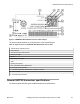


Table Of Contents
- Contents
- Chapter 1: Preface
- Chapter 2: New in this document
- Chapter 3: Safety and equipment care information
- Chapter 4: Supported transceiver, BOCs and DACs
- Chapter 5: Optical routing design
- Chapter 6: SFP
- Chapter 7: SFP+
- SFP+ transceivers
- SFP+ specifications
- SFP+ labels
- General SFP+ specifications
- Supported SFP+ transceivers
- 10GBASE-T SFP+ transceiver
- 10GBASE-LR/LW SFP+ specifications
- 10GBASE-LR/LW SFP+ high temperature (-5 °C to +85 °C) specifications
- 10GBASE-ER/EW SFP+ specifications
- 10GBASE-SR/SW SFP+ specifications
- 10GBASE-SR/SW SFP+ high temperature (0 °C to +85 °C) specifications
- 10GBASE-ZR/ZW SFP+ specifications
- 10GBASE-LRM SFP+ specifications
- 10GBASE-BX SFP+ specifications
- 10GBASE-CX specifications
- Chapter 8: QSFP+
- Chapter 9: QSFP28
- Chapter 10: End of sale transceivers and cables
- Chapter 11: Translations of safety messages
- Class A electromagnetic interference warning statement
- Electrostatic discharge warning statement
- Laser eye safety danger statement
- Laser eye safety connector inspection danger statement
- Connector cleaning safety danger statement
- Optical fiber damage warning statement
- Optical fiber connector damage warning statement
- SFP damage warning statement
- Glossary

Electrostatic alert:
ESD can damage electronic circuits. Do not touch electronic hardware unless you wear a
grounding wrist strap or other static-dissipating device.
Procedure
1. Disconnect the network fiber optic cable from the transceiver connector.
2. Grasp the pull-tab and slide the transceiver out of the module slot.
If the transceiver does not slide easily from the module slot, use a gentle side-to-side rocking
motion while firmly pulling the transceiver from the slot.
3. Remove connector from transceiver and affix dust covers over the fiber optic bore and
connector.
4. Store the transceiver in a safe place until needed.
Important:
If you discard the transceiver, dispose of it according to all national laws and regulations.
QSFP28 transceiver specifications
This section provides technical specifications for the supported 100 Gigabit QSFP28 transceiver
models. Use these specifications to aid in network design.
The Extreme Networks QSFP28 transceivers listed in this document support Digital Diagnostic
Monitoring (DDM). Third party QSFP28 transceivers may support DDM. However, Extreme
Networks does not provide support for DDM related issues on third party transceivers.
Important:
• The VSP switches allow the use of QSFP28 transceivers from any vendor. Extreme
Networks does not provide support for operational issues related to QSFP28 transceivers
that are not listed in this document as supported transceivers. The switch logs the device
as an unsupported or unknown device.
• Extreme Networks recommends using the QSFP28 transceivers documented in this
document as they have been through extensive qualification and testing. Extreme
Networks is not responsible for issues related to third party QSFP28 transceivers.
QSFP28 transceiver labels
A label can be located on either the top or bottom of the typical QSFP28 transceiver. The following
figure shows an example label.
Sometimes alternate labels are used depending on the size of the device and space available for
label information.
QSFP28
May 2018 Installing Transceivers and Optical Components on VOSS 66