
Installation Instructions

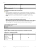


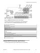


Table Of Contents
- Contents
- Chapter 1: Preface
- Chapter 2: New in this document
- Chapter 3: Safety and equipment care information
- Chapter 4: Supported transceiver, BOCs and DACs
- Chapter 5: Optical routing design
- Chapter 6: SFP
- Chapter 7: SFP+
- SFP+ transceivers
- SFP+ specifications
- SFP+ labels
- General SFP+ specifications
- Supported SFP+ transceivers
- 10GBASE-T SFP+ transceiver
- 10GBASE-LR/LW SFP+ specifications
- 10GBASE-LR/LW SFP+ high temperature (-5 °C to +85 °C) specifications
- 10GBASE-ER/EW SFP+ specifications
- 10GBASE-SR/SW SFP+ specifications
- 10GBASE-SR/SW SFP+ high temperature (0 °C to +85 °C) specifications
- 10GBASE-ZR/ZW SFP+ specifications
- 10GBASE-LRM SFP+ specifications
- 10GBASE-BX SFP+ specifications
- 10GBASE-CX specifications
- Chapter 8: QSFP+
- Chapter 9: QSFP28
- Chapter 10: End of sale transceivers and cables
- Chapter 11: Translations of safety messages
- Class A electromagnetic interference warning statement
- Electrostatic discharge warning statement
- Laser eye safety danger statement
- Laser eye safety connector inspection danger statement
- Connector cleaning safety danger statement
- Optical fiber damage warning statement
- Optical fiber connector damage warning statement
- SFP damage warning statement
- Glossary

Maximum receiver power, each lane in OMA –4 dBm
Receiver sensitivity (OMA), each lane –19 dBm
Stressed receiver sensitivity (OMA), each lane
(max.)
–16.8 dBm
Maximum receiver reflectance –26 dBm
Link Engineering for greater than 30 km operation
Caution:
Operating ranges that are greater than 30 km for the same link power budget are considered
engineered links. If your operating range is greater than 30 km, you require engineering skills to
determine correct device and cable plant specifications, and installation practices. It is
recommended that you consider the potential impact of operating with near zero assured
margin.
The following list provides the requirements for achieving operation to 40 km:
• Ensure fiber insertion loss, in dB/km, is less than (18.5 – connector loss, dB)/length.
• Observe strict limits on number and insertion loss of connectors.
• Note that operation to 40 km can possibly eliminate power margin allocated to aging, additional
connectors, or cable repairs. This increases risk of additional remediation effort in the event of
cable or configuration changes. Cable cuts are the dominant cause of link failure and have
been observed to occur on average 4.39 times per thousand sheath miles per year.
Table 25: 40GBASE-ER4 operating ranges
Required operating range
2 m to 30 km
2 m to 40 km
Interoperation
40GBASE-ER4 and 40GBASE-LR4 QSFP+ transceivers can interoperate with a properly-
engineered link. It requires the cabling (channel) characteristics for 40GBASE-LR4 to be met, with
the exception of the maximum and minimum channel insertion loss values, as shown in the following
table, for the two link directions separately.
Direction
Min. loss Max. loss Unit
40GBASE-LR4
transmitter to 40GBASE-
ER4 receiver
7.5 14.2 dB
40GBASE-ER4
transmitter to 40GBASE-
LR4 receiver
2.2 11 dB
QSFP+
May 2018 Installing Transceivers and Optical Components on VOSS 62