
Installation Instructions


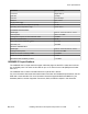
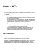
Table Of Contents
- Contents
- Chapter 1: Preface
- Chapter 2: New in this document
- Chapter 3: Safety and equipment care information
- Chapter 4: Supported transceiver, BOCs and DACs
- Chapter 5: Optical routing design
- Chapter 6: SFP
- Chapter 7: SFP+
- SFP+ transceivers
- SFP+ specifications
- SFP+ labels
- General SFP+ specifications
- Supported SFP+ transceivers
- 10GBASE-T SFP+ transceiver
- 10GBASE-LR/LW SFP+ specifications
- 10GBASE-LR/LW SFP+ high temperature (-5 °C to +85 °C) specifications
- 10GBASE-ER/EW SFP+ specifications
- 10GBASE-SR/SW SFP+ specifications
- 10GBASE-SR/SW SFP+ high temperature (0 °C to +85 °C) specifications
- 10GBASE-ZR/ZW SFP+ specifications
- 10GBASE-LRM SFP+ specifications
- 10GBASE-BX SFP+ specifications
- 10GBASE-CX specifications
- Chapter 8: QSFP+
- Chapter 9: QSFP28
- Chapter 10: End of sale transceivers and cables
- Chapter 11: Translations of safety messages
- Class A electromagnetic interference warning statement
- Electrostatic discharge warning statement
- Laser eye safety danger statement
- Laser eye safety connector inspection danger statement
- Connector cleaning safety danger statement
- Optical fiber damage warning statement
- Optical fiber connector damage warning statement
- SFP damage warning statement
- Glossary

The following table lists the transmitter and receiver specifications for the 10GBASE-LRM SFP+
transceiver. The part number of this SFP+ transceiver is AA1403017-E6.
Note:
VSP 7254XSQ has a PHYless design, which is typical for Data Center Top of Rack switches.
The benefits of a PHYless design are lower power consumption and lower latency. However,
due to the PHYless design, this transceiver is not supported.
In this table, the OMA, average launch power, and peak power specifications apply at TP2, after
accounting for patch cord loss.
Table 17: 10GBASE-LRM SFP+ transceiver specifications
Parameter Specifications
Data rate 10 Gbps
Line rate (64B/66B code) 10.3125 Gbps ± 100 ppm
Center wavelength range 1260 to 1355 nm; 1310 nm nominal
Distance Up to 220 m on 62.5 µm MMF
Up to 300 m on SMF
Link optical power budget 1.7 to 1.9 dB
Maximum transmitter waveform and dispersion
penalty (TWDP)
4.7 dB
Transmitter characteristics
Average launch power –6.5 to 0.5 dBm
Peak launch power 3 dBm
Root-mean-square spectral width 2.4 to 4 nm
Launch power in OMA –4.5 to 1.5 dBm
Minimum extinction ratio 3.5 dB
Optical return loss tolerance (minimum) –20 dB
Receiver characteristics
Receiver damage threshold 1.5 dBm
Receiver reflectance (maximum) –12 dB
For more information about the conditions used for the stressed receiver tests, and other
information, see the IEEE 802.3–2012 standard.
The following table (from IEEE 802.3–2012) describes the maximum channel insertion loss. The
channel insertion loss includes both attenuation and connector loss (1.5 dB); therefore the maximum
fiber attenuation is 0.2 to 0.4 dB.
SFP+ specifications
May 2018 Installing Transceivers and Optical Components on VOSS 47