
Design Reference


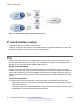
Table Of Contents
- Contents
- Chapter 1: Introduction
- Chapter 2: New in this release
- Chapter 3: Network design fundamentals
- Chapter 4: Hardware fundamentals and guidelines
- Chapter 5: Optical routing design
- Chapter 6: Platform redundancy
- Chapter 7: Link redundancy
- Chapter 8: Layer 2 loop prevention
- Chapter 9: Layer 2 switch clustering and SMLT
- Chapter 10: Layer 3 switch clustering and RSMLT
- Chapter 11: Layer 3 switch clustering and multicast SMLT
- Chapter 12: Spanning tree
- Chapter 13: Layer 3 network design
- Chapter 14: SPBM design guidelines
- Chapter 15: IP multicast network design
- Multicast and VRF-Lite
- Multicast and MultiLink Trunking considerations
- Multicast scalability design rules
- IP multicast address range restrictions
- Multicast MAC address mapping considerations
- Dynamic multicast configuration changes
- IGMPv3 backward compatibility
- IGMP Layer 2 Querier
- TTL in IP multicast packets
- Multicast MAC filtering
- Guidelines for multicast access policies
- Split-subnet and multicast
- Protocol Independent Multicast-Sparse Mode guidelines
- Protocol Independent Multicast-Source Specific Multicast guidelines
- Multicast for multimedia
- Chapter 16: System and network stability and security
- Chapter 17: QoS design guidelines
- Chapter 18: Layer 1, 2, and 3 design examples
- Glossary

Figure 38: BGP and edge aggregation
BGP and ISP segmentation
You can use the platform as a peering point between different regions or ASs that belong to the
same ISP. In such cases, you can define a region as an OSPF area, an AS, or a part of an AS.
You can divide the AS into multiple regions that each run different IGPs. Interconnect regions
logically by using a full iBGP mesh. Each region then injects its IGP routes into iBGP and also
injects a default route inside the region. For destinations that do not belong to the region, each
region defaults to the BGP border router.
Use the community parameter to differentiate between regions. To provide Internet connectivity, this
scenario requires you to make your Internet connections part of the central iBGP mesh (see the
following figure).
Figure 39: Multiple regions separated by iBGP
Layer 3 network design
88 Network Design Reference for Avaya VSP 4000 Series June 2015
Comments on this document? infodev@avaya.com