
Design Reference


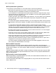


Table Of Contents
- Contents
- Chapter 1: Introduction
- Chapter 2: New in this release
- Chapter 3: Network design fundamentals
- Chapter 4: Hardware fundamentals and guidelines
- Chapter 5: Optical routing design
- Chapter 6: Platform redundancy
- Chapter 7: Link redundancy
- Chapter 8: Layer 2 loop prevention
- Chapter 9: Layer 2 switch clustering and SMLT
- Chapter 10: Layer 3 switch clustering and RSMLT
- Chapter 11: Layer 3 switch clustering and multicast SMLT
- Chapter 12: Spanning tree
- Chapter 13: Layer 3 network design
- Chapter 14: SPBM design guidelines
- Chapter 15: IP multicast network design
- Multicast and VRF-Lite
- Multicast and MultiLink Trunking considerations
- Multicast scalability design rules
- IP multicast address range restrictions
- Multicast MAC address mapping considerations
- Dynamic multicast configuration changes
- IGMPv3 backward compatibility
- IGMP Layer 2 Querier
- TTL in IP multicast packets
- Multicast MAC filtering
- Guidelines for multicast access policies
- Split-subnet and multicast
- Protocol Independent Multicast-Sparse Mode guidelines
- Protocol Independent Multicast-Source Specific Multicast guidelines
- Multicast for multimedia
- Chapter 16: System and network stability and security
- Chapter 17: QoS design guidelines
- Chapter 18: Layer 1, 2, and 3 design examples
- Glossary

2. Configure OSPF on one network.
On S1, insert the IP address, subnet mask, and VLAN ID for the OSPF port. Enable OSPF
on the port. On S2, insert the IP address, subnet mask, and VLAN ID for the OSPF port in
area 1, and enable OSPF on the port. Both routable ports belong to the same network.
Therefore, by default, both ports are in the same area.
3. Configure three OSPF areas for the network.
4. Configure OSPF on two additional ports in a second subnet.
Configure additional ports and verify that IP forwarding is enabled for each switch to ensure
that routing can occur. On S2, insert the IP address, subnet mask, and VLAN ID for the
OSPF port in area 2, and enable OSPF on the port. On S3, insert the IP address, subnet
mask, and VLAN ID for the OSPF port, and enable OSPF on the port.
The three switches exchange hello packets.
In an environment with a mix of non-Avaya and Avaya switches and routers, you may need to
manually modify the OSPF parameter RtrDeadInterval to 40 seconds.
Border Gateway Protocol
Use the Border Gateway Protocol (BGP) to ensure that the switch can communicate with other BGP
routers on the Internet backbone. BGP is an exterior gateway protocol that exchanges network
reachability information with other BGP systems in the same or other autonomous systems (AS).
This network reachability information includes information about the AS list that the reachability
information traverses. By using this information, you can prune routing loops and enforce policy
decisions at the AS level.
BGP performs routing between two sets of routers that operate in different autonomous systems. An
AS can use two kinds of BGP: internal BGP (iBGP), which refers to the protocol that BGP routers
use within an autonomous system, and external BGP (eBGP), which refers to the protocol that BGP
routers use across two different autonomous systems. BGP information is redistributed to Interior
Gateway Protocols (IGP) that run in the autonomous system.
BGP version 4 (BGPv4) supports classless interdomain routing (CIDR). BGPv4 advertises the IP
prefix and eliminates the concept of network class within BGP. BGPv4 can aggregate routes and AS
paths. BGP aggregation does not occur when routes have different Multi-Exit Discriminators (MED)
or next hops.
BGP Equal-Cost Multipath (ECMP) allows a BGP speaker to perform route balancing within an AS
by using multiple equal-cost routes submitted to the routing table by OSPF or RIP. BGP performs
load balancing on an individual-packet basis.
To control route propagation and filtering, RFC1772 and RFC2270 recommend that multihomed,
nontransit autonomous systems not run BGPv4. To address the load sharing and reliability
requirements of a multihomed user, use BGP between them.
For more information about BGP concepts and configuration, see Configuring BGP on Avaya Virtual
Services Platform 4000 Series, NN46251-507.
Border Gateway Protocol
June 2015 Network Design Reference for Avaya VSP 4000 Series 85
Comments on this document? infodev@avaya.com