
Design Reference


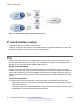
Table Of Contents
- Contents
- Chapter 1: Introduction
- Chapter 2: New in this release
- Chapter 3: Network design fundamentals
- Chapter 4: Hardware fundamentals and guidelines
- Chapter 5: Optical routing design
- Chapter 6: Platform redundancy
- Chapter 7: Link redundancy
- Chapter 8: Layer 2 loop prevention
- Chapter 9: Layer 2 switch clustering and SMLT
- Chapter 10: Layer 3 switch clustering and RSMLT
- Chapter 11: Layer 3 switch clustering and multicast SMLT
- Chapter 12: Spanning tree
- Chapter 13: Layer 3 network design
- Chapter 14: SPBM design guidelines
- Chapter 15: IP multicast network design
- Multicast and VRF-Lite
- Multicast and MultiLink Trunking considerations
- Multicast scalability design rules
- IP multicast address range restrictions
- Multicast MAC address mapping considerations
- Dynamic multicast configuration changes
- IGMPv3 backward compatibility
- IGMP Layer 2 Querier
- TTL in IP multicast packets
- Multicast MAC filtering
- Guidelines for multicast access policies
- Split-subnet and multicast
- Protocol Independent Multicast-Sparse Mode guidelines
- Protocol Independent Multicast-Source Specific Multicast guidelines
- Multicast for multimedia
- Chapter 16: System and network stability and security
- Chapter 17: QoS design guidelines
- Chapter 18: Layer 1, 2, and 3 design examples
- Glossary

Figure 32: Avoiding excessive ICMP redirect messages without SMLT
Open Shortest Path First
Use OSPF to ensure that the switch can communicate with other OSPF routers. This section
describes some general design considerations and presents a number of design scenarios for
OSPF.
For more information about OSPF concepts and configuration, see Configuring OSPF and RIP on
Avaya Virtual Services Platform 4000 Series, NN46251-506.
OSPF LSA limits
To determine OSPF link-state advertisement (LSA) limits:
1. Use the command show ip ospf area to determine the LSA_CNT and to obtain the
number of LSAs for a given area.
2. Use the following formula to determine the number of areas. Ensure the total is less than
16,000 (16K):
N = 1 to the number of areas for each switch
Adj
N
= number of adjacencies for each Area N
LSA_CNT
N
= number of LSAs for each Area N
For example, assume that a switch has a configuration of three areas with a total of 18 adjacencies
and 1000 routes. This includes:
• 3 adjacencies with an LSA_CNT of 500 (Area 1)
• 10 adjacencies with an LSA_CNT of 1000 (Area 2)
Open Shortest Path First
June 2015 Network Design Reference for Avaya VSP 4000 Series 81
Comments on this document? infodev@avaya.com