
Design Reference


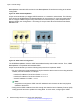

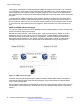
Table Of Contents
- Contents
- Chapter 1: Introduction
- Chapter 2: New in this release
- Chapter 3: Network design fundamentals
- Chapter 4: Hardware fundamentals and guidelines
- Chapter 5: Optical routing design
- Chapter 6: Platform redundancy
- Chapter 7: Link redundancy
- Chapter 8: Layer 2 loop prevention
- Chapter 9: Layer 2 switch clustering and SMLT
- Chapter 10: Layer 3 switch clustering and RSMLT
- Chapter 11: Layer 3 switch clustering and multicast SMLT
- Chapter 12: Spanning tree
- Chapter 13: Layer 3 network design
- Chapter 14: SPBM design guidelines
- Chapter 15: IP multicast network design
- Multicast and VRF-Lite
- Multicast and MultiLink Trunking considerations
- Multicast scalability design rules
- IP multicast address range restrictions
- Multicast MAC address mapping considerations
- Dynamic multicast configuration changes
- IGMPv3 backward compatibility
- IGMP Layer 2 Querier
- TTL in IP multicast packets
- Multicast MAC filtering
- Guidelines for multicast access policies
- Split-subnet and multicast
- Protocol Independent Multicast-Sparse Mode guidelines
- Protocol Independent Multicast-Source Specific Multicast guidelines
- Multicast for multimedia
- Chapter 16: System and network stability and security
- Chapter 17: QoS design guidelines
- Chapter 18: Layer 1, 2, and 3 design examples
- Glossary

access the Internet, data storage, VoIP-PSTN, or call signaling services. To interconnect VRF
instances, you can use an external firewall that supports virtualization, or use inter-VRF forwarding
for specific services. Using the inter-VRF solution, you can use routing policies and static routes to
inject IP subnets from one VRF instance to another, and filters to restrict access to certain protocols.
The following figure shows inter-VRF forwarding. In this solution, you can use routing policies to leak
IP subnets from one VRF to another. You can use filters to restrict access to certain protocols. This
configuration enables hub-and-spoke network designs, for example, for VoIP gateways.
Figure 27: Inter VRF communication, internal inter-VRF forwarding
Virtual Router Redundancy Protocol
The Virtual Router Redundancy Protocol (VRRP) provides a backup router that takes over if a router
fails, which is important if you must provide redundancy mechanisms.
VRRP guidelines
VRRP provides another layer of resiliency to your network design by providing default gateway
redundancy for end users. If a VRRP-enabled router that connects to the default gateway fails,
failover to the VRRP backup router ensures no interruption for end users who attempt to route from
their local subnet.
Only the VRRP Master router forwards traffic for a given subnet. The backup VRRP router does not
route traffic destined for the default gateway.
To allow both VRRP switches to route traffic, VSP 4000 has an extension to VRRP, the
BackupMaster, that creates an active-active environment for routing. If you enable BackupMaster on
the backup router, the backup router no longer switches traffic to the VRRP Master. Instead the
Virtual Router Redundancy Protocol
June 2015 Network Design Reference for Avaya VSP 4000 Series 77
Comments on this document? infodev@avaya.com