
Design Reference


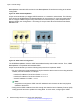

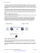
Table Of Contents
- Contents
- Chapter 1: Introduction
- Chapter 2: New in this release
- Chapter 3: Network design fundamentals
- Chapter 4: Hardware fundamentals and guidelines
- Chapter 5: Optical routing design
- Chapter 6: Platform redundancy
- Chapter 7: Link redundancy
- Chapter 8: Layer 2 loop prevention
- Chapter 9: Layer 2 switch clustering and SMLT
- Chapter 10: Layer 3 switch clustering and RSMLT
- Chapter 11: Layer 3 switch clustering and multicast SMLT
- Chapter 12: Spanning tree
- Chapter 13: Layer 3 network design
- Chapter 14: SPBM design guidelines
- Chapter 15: IP multicast network design
- Multicast and VRF-Lite
- Multicast and MultiLink Trunking considerations
- Multicast scalability design rules
- IP multicast address range restrictions
- Multicast MAC address mapping considerations
- Dynamic multicast configuration changes
- IGMPv3 backward compatibility
- IGMP Layer 2 Querier
- TTL in IP multicast packets
- Multicast MAC filtering
- Guidelines for multicast access policies
- Split-subnet and multicast
- Protocol Independent Multicast-Sparse Mode guidelines
- Protocol Independent Multicast-Source Specific Multicast guidelines
- Multicast for multimedia
- Chapter 16: System and network stability and security
- Chapter 17: QoS design guidelines
- Chapter 18: Layer 1, 2, and 3 design examples
- Glossary

Figure 24: VLAN isolation
MSTP and RSTP considerations
The Spanning Tree Protocol (STP) provides loop protection and recovery, but it is slow to respond
to a topology change in the network (for example, a dysfunctional link in a network). RSTP (IEEE
802.1w) and MSTP (IEEE 802.1s) reduce the recovery time after a network failure. RSTP and
MSTP also maintain a backward compatibility with IEEE 802.1D. Typically, the recovery time of
RSTP and MSTP is less than 1 second. RSTP and MSTP also reduce the amount of flooding in the
network by enhancing the way that Topology Change Notification (TCN) packets are generated.
Use MSTP to configure MSTIs on the same switch. Each MSTI can include one or more VLANs.
In MSTP mode you can configure up to 64 instances. Instance 0 or Common and Internal Spanning
Tree (CIST) is the default group, which includes default VLAN 1. Instances 1 to 63 are MSTIs.
MSTP and RSTP considerations
June 2015 Network Design Reference for Avaya VSP 4000 Series 73
Comments on this document? infodev@avaya.com