
Design Reference
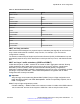


Table Of Contents
- Contents
- Chapter 1: Introduction
- Chapter 2: New in this release
- Chapter 3: Network design fundamentals
- Chapter 4: Hardware fundamentals and guidelines
- Chapter 5: Optical routing design
- Chapter 6: Platform redundancy
- Chapter 7: Link redundancy
- Chapter 8: Layer 2 loop prevention
- Chapter 9: Layer 2 switch clustering and SMLT
- Chapter 10: Layer 3 switch clustering and RSMLT
- Chapter 11: Layer 3 switch clustering and multicast SMLT
- Chapter 12: Spanning tree
- Chapter 13: Layer 3 network design
- Chapter 14: SPBM design guidelines
- Chapter 15: IP multicast network design
- Multicast and VRF-Lite
- Multicast and MultiLink Trunking considerations
- Multicast scalability design rules
- IP multicast address range restrictions
- Multicast MAC address mapping considerations
- Dynamic multicast configuration changes
- IGMPv3 backward compatibility
- IGMP Layer 2 Querier
- TTL in IP multicast packets
- Multicast MAC filtering
- Guidelines for multicast access policies
- Split-subnet and multicast
- Protocol Independent Multicast-Sparse Mode guidelines
- Protocol Independent Multicast-Source Specific Multicast guidelines
- Multicast for multimedia
- Chapter 16: System and network stability and security
- Chapter 17: QoS design guidelines
- Chapter 18: Layer 1, 2, and 3 design examples
- Glossary

Table 17: Recommended VLACP values
Parameter Value
SMLT access
Timeout Short
Timer 500ms
Timeout scale 5
VLACP MAC 01:80:C2:00:00:0F
SMLT core
Timeout Short
Timer 500ms
Timeout scale 5
VLACP MAC 01:80:C2:00:00:0F
vIST
Timeout Long
Timer 10000
Timeout scale 3
VLACP MAC 01:80:C2:00:00:0F
SMLT and loop prevention
SMLT-based network designs form physical loops for redundancy that logically do not function as
loops. Under certain adverse conditions, loops can form, for example, if you use incorrect
configurations or cabling.
The solution to detect loops is Simple Loop Prevention Protocol (SLPP). SLPP detects a loop and
automatically stops the loop. SLPP determines on which port the loop occurs, and shuts down that
port.
SMLT and Layer 3 traffic redundancy (VRRP and RSMLT)
VLANs that are part of an SMLT network can be routed on SMLT aggregation switches. Routing
VLANs enables the SMLT edge network to connect to other Layer 3 networks. Virtual Router
Redundancy Protocol (VRRP), which provides redundant default gateway configurations,
additionally has BackupMaster capability. BackupMaster improves the Layer 3 capabilities of VRRP
operating in conjunction with SMLT. Use a VRRP BackupMaster configuration with an SMLT
configuration that currently uses VRRP.
Important:
Avaya strongly recommends using Routed SMLT (RSMLT) Layer 2 Edge configuration as a
better alternative to SMLT with VRRP BackupMaster. Unless it is specifically required, use an
RSMLT configuration.
RSMLT Layer 2 Edge configurations provide:
• Greater scalability — RSMLT scales to the maximum number of VLANs, while VRRP scales to
255 for each VRF and 512 for each system. VRRP IDs 1-255 are unique to each VLAN.
Split MultiLink Trunk configuration
June 2015 Network Design Reference for Avaya VSP 4000 Series 51
Comments on this document? infodev@avaya.com