
Design Reference


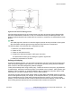


Table Of Contents
- Contents
- Chapter 1: Introduction
- Chapter 2: New in this release
- Chapter 3: Network design fundamentals
- Chapter 4: Hardware fundamentals and guidelines
- Chapter 5: Optical routing design
- Chapter 6: Platform redundancy
- Chapter 7: Link redundancy
- Chapter 8: Layer 2 loop prevention
- Chapter 9: Layer 2 switch clustering and SMLT
- Chapter 10: Layer 3 switch clustering and RSMLT
- Chapter 11: Layer 3 switch clustering and multicast SMLT
- Chapter 12: Spanning tree
- Chapter 13: Layer 3 network design
- Chapter 14: SPBM design guidelines
- Chapter 15: IP multicast network design
- Multicast and VRF-Lite
- Multicast and MultiLink Trunking considerations
- Multicast scalability design rules
- IP multicast address range restrictions
- Multicast MAC address mapping considerations
- Dynamic multicast configuration changes
- IGMPv3 backward compatibility
- IGMP Layer 2 Querier
- TTL in IP multicast packets
- Multicast MAC filtering
- Guidelines for multicast access policies
- Split-subnet and multicast
- Protocol Independent Multicast-Sparse Mode guidelines
- Protocol Independent Multicast-Source Specific Multicast guidelines
- Multicast for multimedia
- Chapter 16: System and network stability and security
- Chapter 17: QoS design guidelines
- Chapter 18: Layer 1, 2, and 3 design examples
- Glossary

active on core ports, the level of service received is based on the highest of the DiffServ or 802.1p
settings.
The following cases provide sample QoS design guidelines you can use to provide and maintain
high service quality in a network.
If you configure a core port, you assume that, for all incoming traffic, the QoS value is properly
marked. All core switch ports simply read and forward packets; they are not re-marked or
reclassified. All initial QoS markings are performed at the customer device or on the edge devices.
The following figure illustrates the actions performed on three different bridged traffic flows (that is
VoIP, video conference, and email) at access and core ports throughout the network.
Figure 81: Trusted bridged traffic
For bridged, untrusted traffic, if you configure the port to access, mark and prioritize traffic on the
access node using global filters. Reclassify the traffic to ensure it complies with the class of service
specified in the SLA.
For Resilient Packet Ring (RPR) interworking, you can assume that, for all incoming traffic, the QoS
configuration is properly marked by the access nodes. The core switch ports, configured as core or
trunk ports, perform the RPR interworking. These ports preserve the DSCP marking and re-mark the
802.1p bit to match the 802.1p bit of the RPR. The following figure shows the actions performed on
three different traffic flows (VoIP, video conference, and email) over an RPR core network.
QoS examples and recommendations
June 2015 Network Design Reference for Avaya VSP 4000 Series 167
Comments on this document? infodev@avaya.com