
Design Reference


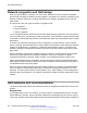


Table Of Contents
- Contents
- Chapter 1: Introduction
- Chapter 2: New in this release
- Chapter 3: Network design fundamentals
- Chapter 4: Hardware fundamentals and guidelines
- Chapter 5: Optical routing design
- Chapter 6: Platform redundancy
- Chapter 7: Link redundancy
- Chapter 8: Layer 2 loop prevention
- Chapter 9: Layer 2 switch clustering and SMLT
- Chapter 10: Layer 3 switch clustering and RSMLT
- Chapter 11: Layer 3 switch clustering and multicast SMLT
- Chapter 12: Spanning tree
- Chapter 13: Layer 3 network design
- Chapter 14: SPBM design guidelines
- Chapter 15: IP multicast network design
- Multicast and VRF-Lite
- Multicast and MultiLink Trunking considerations
- Multicast scalability design rules
- IP multicast address range restrictions
- Multicast MAC address mapping considerations
- Dynamic multicast configuration changes
- IGMPv3 backward compatibility
- IGMP Layer 2 Querier
- TTL in IP multicast packets
- Multicast MAC filtering
- Guidelines for multicast access policies
- Split-subnet and multicast
- Protocol Independent Multicast-Sparse Mode guidelines
- Protocol Independent Multicast-Source Specific Multicast guidelines
- Multicast for multimedia
- Chapter 16: System and network stability and security
- Chapter 17: QoS design guidelines
- Chapter 18: Layer 1, 2, and 3 design examples
- Glossary

Chapter 17: QoS design guidelines
This chapter provides design guidelines to provide Quality of Service (QoS) to user traffic on the
network.
For more information about fundamental QoS mechanisms and how to configure QoS, see
Configuration - QoS and ACL-Based Traffic Filtering Avaya Virtual Services Platform 4000 Series,
NN46251-502.
QoS mechanisms
Avaya Virtual Services Platform 4000 Series has a solid, well-defined architecture to handle QoS in
an efficient and effective manner. The following sections briefly describe several QoS mechanisms
that the platform uses.
QoS classification and mapping
VSP 4000 provides a hardware-based QoS platform through hardware packet classification. Packet
classification is based on the examination of the QoS fields within the Ethernet packet, primarily the
Differentiated Services Code Point (DSCP) and the 802.1p fields.
You can configure ingress interfaces in one of two ways. In the first type of configuration, the
interface does not classify traffic, but it forwards the traffic based on the packet markings. This mode
of operation applies to trusted interfaces (core port mode) because the DSCP or 802.1p field is
trusted to be correct, and the edge switch performs the mapping without classification.
In the second type of configuration, the interface classifies traffic as it enters the port, and marks the
packet for further treatment as it traverses VSP 4000 network. This mode of operation applies to
untrusted interfaces (access port mode) because the DSCP or 802.1p field is not trusted to be
correct.
VSP 4000 assigns an internal QoS level to each packet that enters a port.
The Avaya QoS strategy simplifies QoS implementation by providing a mapping of various traffic
types and categories to a Class of Service. These service classes are termed Avaya Service
Classes (ASC). The following table provides a summary of the mappings and their typical traffic
types.
June 2015 Network Design Reference for Avaya VSP 4000 Series 161
Comments on this document? infodev@avaya.com