
Design Reference


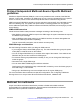


Table Of Contents
- Contents
- Chapter 1: Introduction
- Chapter 2: New in this release
- Chapter 3: Network design fundamentals
- Chapter 4: Hardware fundamentals and guidelines
- Chapter 5: Optical routing design
- Chapter 6: Platform redundancy
- Chapter 7: Link redundancy
- Chapter 8: Layer 2 loop prevention
- Chapter 9: Layer 2 switch clustering and SMLT
- Chapter 10: Layer 3 switch clustering and RSMLT
- Chapter 11: Layer 3 switch clustering and multicast SMLT
- Chapter 12: Spanning tree
- Chapter 13: Layer 3 network design
- Chapter 14: SPBM design guidelines
- Chapter 15: IP multicast network design
- Multicast and VRF-Lite
- Multicast and MultiLink Trunking considerations
- Multicast scalability design rules
- IP multicast address range restrictions
- Multicast MAC address mapping considerations
- Dynamic multicast configuration changes
- IGMPv3 backward compatibility
- IGMP Layer 2 Querier
- TTL in IP multicast packets
- Multicast MAC filtering
- Guidelines for multicast access policies
- Split-subnet and multicast
- Protocol Independent Multicast-Sparse Mode guidelines
- Protocol Independent Multicast-Source Specific Multicast guidelines
- Multicast for multimedia
- Chapter 16: System and network stability and security
- Chapter 17: QoS design guidelines
- Chapter 18: Layer 1, 2, and 3 design examples
- Glossary

Figure 72: Receivers on interconnected VLANs
IGMP reports that the messages that the receiver sends are forwarded to the DR, and both A and B
create (*,G) records. Switch A receives duplicate data through the path from C to A, and through the
second path from C to B to A. Switch A discards the data on the second path (assuming the
upstream source is A to C).
To avoid this waste of resources, Avaya recommends that you do not place receivers on V1. This
configuration guarantees that no traffic flows between B and A for receivers attached to A. In this
case, the existence of the receivers is only learned through PIM join messages to the RP [for (*,G)]
and of the source through SPT joins.
PIM network with non-PIM interfaces
For proper multicast traffic flow in a PIM-SM domain, as a general rule, enable PIM-SM on all
interfaces in the network (even if paths exist between all PIM interfaces). Enable PIM on all
interfaces because PIM-SM relies on the unicast routing table to determine the path to the RP, BSR,
and multicast sources. Ensure that all routers on these paths have PIM-SM enabled interfaces.
The following figure provides an example of this situation. If A is the RP, then initially the receiver
receives data from the shared tree path (that is, through switch A).
Protocol Independent Multicast-Sparse Mode guidelines
June 2015 Network Design Reference for Avaya VSP 4000 Series 143
Comments on this document? infodev@avaya.com