
Design Reference

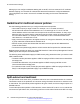


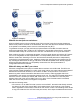


Table Of Contents
- Contents
- Chapter 1: Introduction
- Chapter 2: New in this release
- Chapter 3: Network design fundamentals
- Chapter 4: Hardware fundamentals and guidelines
- Chapter 5: Optical routing design
- Chapter 6: Platform redundancy
- Chapter 7: Link redundancy
- Chapter 8: Layer 2 loop prevention
- Chapter 9: Layer 2 switch clustering and SMLT
- Chapter 10: Layer 3 switch clustering and RSMLT
- Chapter 11: Layer 3 switch clustering and multicast SMLT
- Chapter 12: Spanning tree
- Chapter 13: Layer 3 network design
- Chapter 14: SPBM design guidelines
- Chapter 15: IP multicast network design
- Multicast and VRF-Lite
- Multicast and MultiLink Trunking considerations
- Multicast scalability design rules
- IP multicast address range restrictions
- Multicast MAC address mapping considerations
- Dynamic multicast configuration changes
- IGMPv3 backward compatibility
- IGMP Layer 2 Querier
- TTL in IP multicast packets
- Multicast MAC filtering
- Guidelines for multicast access policies
- Split-subnet and multicast
- Protocol Independent Multicast-Sparse Mode guidelines
- Protocol Independent Multicast-Source Specific Multicast guidelines
- Multicast for multimedia
- Chapter 16: System and network stability and security
- Chapter 17: QoS design guidelines
- Chapter 18: Layer 1, 2, and 3 design examples
- Glossary

Figure 68: Multicast SMLT triangle
Consider an example where one of the peers, vIST-A, is the PIM DR for the source VLAN, and the
source data is hashed to vIST-A from the Layer 2 source edge. vIST-A forwards traffic to the
receiver edge using the SMLT link from vIST-A to the receiver edge. If the SMLT link fails, vIST-A
does not forward traffic over the vIST link to vIST-B, and the receiver edge does receive the data.
In this topology, the receiver edge sends an IGMP membership report for a group, which is recorded
on both vIST peers as an IGMP LEAF on the receiver SMLT port on the receiver VLAN.
Because both of the vIST peers are the RP for the group, they do not send a (*,g) PIM JOIN
message toward the other RP. The (*,g) PIM mroute does not record the vIST port as a JOIN port
on either vIST device. The PIM (*,g) mroute records only a LEAF on the SMLT receiver port.
Because the source is local (Layer 2 edge), there is no PIM (s,g) JOIN message toward the source
and the (s,g) PIM mroute does not record the vIST port as a JOIN port on either vIST device. The
PIM (s,g) mroute records only a LEAF on the SMLT receiver port.
If the source is hashed to vIST-A, the PIM DR for the incoming VLAN, traffic is forwarded to the
receiver correctly. vIST-A does not forward traffic over the vIST to vIST-B, because no JOIN exists
on the vIST port. If the receiver SMLT link from the vIST-A peer is down, the traffic is not forwarded
to vIST-B, and is not received by the receiver edge. Traffic resumes after the link is restored. If the
source data hashes to the non-DR peer, vIST-B, no problem occurs because the non-DR always
forwards traffic to the DR.
A similar situation exists in this topology when vIST-A is both the RP and the DR for the Layer 2
receiver edge. The vIST port is not in the outgoing port list because there is no JOIN message from
the peer toward the source (which is not PIM enabled). Therefore, if the SMLT link from vIST-A to
the receiver edge is down, the system does not forward traffic to the peer vIST-B and down to the
receiver.
You can avoid the preceding problems with this topology by performing one of the following actions:
• Enable PIM on the source edge.
The vIST peers send PIM joins toward the source and the JOIN is recorded on the vIST port for
the (s,g). Data is forwarded to the peer.
Protocol Independent Multicast-Sparse Mode guidelines
June 2015 Network Design Reference for Avaya VSP 4000 Series 137
Comments on this document? infodev@avaya.com