
Design Reference


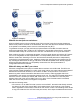


Table Of Contents
- Contents
- Chapter 1: Introduction
- Chapter 2: New in this release
- Chapter 3: Network design fundamentals
- Chapter 4: Hardware fundamentals and guidelines
- Chapter 5: Optical routing design
- Chapter 6: Platform redundancy
- Chapter 7: Link redundancy
- Chapter 8: Layer 2 loop prevention
- Chapter 9: Layer 2 switch clustering and SMLT
- Chapter 10: Layer 3 switch clustering and RSMLT
- Chapter 11: Layer 3 switch clustering and multicast SMLT
- Chapter 12: Spanning tree
- Chapter 13: Layer 3 network design
- Chapter 14: SPBM design guidelines
- Chapter 15: IP multicast network design
- Multicast and VRF-Lite
- Multicast and MultiLink Trunking considerations
- Multicast scalability design rules
- IP multicast address range restrictions
- Multicast MAC address mapping considerations
- Dynamic multicast configuration changes
- IGMPv3 backward compatibility
- IGMP Layer 2 Querier
- TTL in IP multicast packets
- Multicast MAC filtering
- Guidelines for multicast access policies
- Split-subnet and multicast
- Protocol Independent Multicast-Sparse Mode guidelines
- Protocol Independent Multicast-Source Specific Multicast guidelines
- Multicast for multimedia
- Chapter 16: System and network stability and security
- Chapter 17: QoS design guidelines
- Chapter 18: Layer 1, 2, and 3 design examples
- Glossary

that the remote SMLT is up and therefore the remote peer has already forwarded the data. If
the forwarding switch goes down, the other switch receives the data directly over its source
SMLT link and takes over forwarding to the receivers. After the original switch comes back up,
the original switch again receives the data directly over its source SMLT. The original switch
may not be ready to forward the data because of the protocol reconvergence, so the original
switch loses traffic until reconvergence is complete.
• If the source is not learned on another SMLT link or the vIST link on each aggregate switch;
they have a route to the source which is not on an SMLT or across the vIST. The switches
must choose which one forwards the data down the receiver SMLT link; which one is the
designated forwarder, so that duplicate data does not occur. The highest IP address is the
designated forwarder. If the designated forwarder becomes disabled, the other takes over.
When it is reenabled, the other switch sees that it is no longer the highest IP address and it
sees that the remote SMLT link comes up. The other switch then assumes that the vIST peer is
capable of being the designated forwarder and it stops forwarding down to the receivers. If the
original switch is not ready to forward the data due to reconvergence, traffic loss occurs.
In either case, configuring a static RP helps the situation. To avoid this traffic delay, a workaround is
to configure a static RP on the peer SMLT switches. This configuration avoids the process of
selecting an active RP router from the list of candidate RPs, and also of dynamically learning about
RPs through the BSR mechanism. Then, when the DR comes back, traffic resumes as soon as
OSPF converges. This workaround reduces the traffic delay.
Circuitless IP for PIM-SM
Use CLIP to configure a resilient RP and BSR for a PIM network. When you configure an RP or
BSR on a regular interface, if it becomes nonoperational, the RP and BSR also become
nonoperational. This status results in the election of other redundant RPs and BSRs, and can
disrupt IP multicast traffic flow in the network. As a best practice for multicast networks design,
always configure the RP and BSR on a CLIP interface to prevent a single interface failure from
causing these entities to fail.
Avaya also recommends that you configure redundant RPs and BSRs on different switches and that
these entities be on CLIP interfaces. For the successful setup of multicast streams, ensure that a
unicast route exists to all CLIP interfaces from all locations in the network. A unicast route is
mandatory because, for proper RP learning and stream setup on the shared RP tree, every switch in
the network needs to reach the RP and BSR. You can use PIM-SM CLIP interfaces only for RP and
BSR configurations, and are not intended for other purposes.
It is not recommended to have non-SMLT IGMP leaf ports on a VSP router configured to be one of
the redundant RP CLIP devices. It is possible that these IGMP hosts can become isolated from the
multicast data stream(s).
If you configure dual-redundant RPs (vIST peers with the same CLIP interface IP address used for
the RP), the topology in the following figure does not work in link-failure scenarios. Use caution if
you design a network with this topology where the vIST peers are PIM enabled, and the source and
receiver edges are Layer 2.
IP multicast network design
136 Network Design Reference for Avaya VSP 4000 Series June 2015
Comments on this document? infodev@avaya.com