
Design Reference


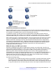


Table Of Contents
- Contents
- Chapter 1: Introduction
- Chapter 2: New in this release
- Chapter 3: Network design fundamentals
- Chapter 4: Hardware fundamentals and guidelines
- Chapter 5: Optical routing design
- Chapter 6: Platform redundancy
- Chapter 7: Link redundancy
- Chapter 8: Layer 2 loop prevention
- Chapter 9: Layer 2 switch clustering and SMLT
- Chapter 10: Layer 3 switch clustering and RSMLT
- Chapter 11: Layer 3 switch clustering and multicast SMLT
- Chapter 12: Spanning tree
- Chapter 13: Layer 3 network design
- Chapter 14: SPBM design guidelines
- Chapter 15: IP multicast network design
- Multicast and VRF-Lite
- Multicast and MultiLink Trunking considerations
- Multicast scalability design rules
- IP multicast address range restrictions
- Multicast MAC address mapping considerations
- Dynamic multicast configuration changes
- IGMPv3 backward compatibility
- IGMP Layer 2 Querier
- TTL in IP multicast packets
- Multicast MAC filtering
- Guidelines for multicast access policies
- Split-subnet and multicast
- Protocol Independent Multicast-Sparse Mode guidelines
- Protocol Independent Multicast-Source Specific Multicast guidelines
- Multicast for multimedia
- Chapter 16: System and network stability and security
- Chapter 17: QoS design guidelines
- Chapter 18: Layer 1, 2, and 3 design examples
- Glossary

Figure 67: Example 2
PIM and shortest path tree switchover
When an IGMP receiver joins a multicast group, PIM on the leaf router first joins the shared tree.
After the first packet is received on the shared tree, the router uses the source address information
in the packet to immediately switch over to the shortest path tree (SPT).
To guarantee a simple, yet high-performance implementation of PIM-SM, the switch does not
support a threshold bit rate in relation to SPT switchover. Intermediate routers (that is, not directly
connected IGMP hosts) do not switch over to the SPT until directed to do so by the leaf routers.
Other vendors can offer a configurable threshold, such as a certain bit rate at which the SPT switch-
over occurs. Regardless of their implementation, no interoperability issues with Virtual Services
Platform 4000 result. Switching to and from the shared and shortest path trees is independently
controlled by each downstream router. Upstream routers relay joins and prunes upstream hop-by-
hop, building the desired tree as they go. Because a PIM-SM compatible router already supports
shared and shortest path trees, no compatibility issues arise from the implementation of
configurable switchover thresholds.
PIM traffic delay and SMLT peer reboot
PIM uses a designated router (DR) to forward data to receivers on the DR VLAN. The DR is the
router with the highest IP address on a LAN. If this router is down, the router with the next highest IP
address becomes the DR. However, if the VLAN is an SMLT VLAN, the DR is not a factor in
determining which switch forwards the data down to the receiver. Either aggregate switch can
forward data to the receiver, because the switches act as one. The switch that forwards depends on
where the source is located (on another SMLT/vIST link or on a non-SMLT/non-vIST link) and
whether either side of the receiver SMLT link is up or down. If the forwarder switch is rebooted,
traffic loss occurs until protocol convergence is completed.
Consider the following cases:
• If the source is on an SMLT link that is not the receiver SMLT, the switch that directly received
the data on its side of the source SMLT link forwards it down to the receiver on the receiver
SMLT regardless of which switch is the DR for the receiver VLAN. The forwarding switch sends
a copy of the data over the vIST link to the peer switch, which drops the data because it knows
Protocol Independent Multicast-Sparse Mode guidelines
June 2015 Network Design Reference for Avaya VSP 4000 Series 135
Comments on this document? infodev@avaya.com