
Design Reference

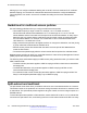


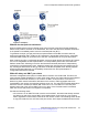


Table Of Contents
- Contents
- Chapter 1: Introduction
- Chapter 2: New in this release
- Chapter 3: Network design fundamentals
- Chapter 4: Hardware fundamentals and guidelines
- Chapter 5: Optical routing design
- Chapter 6: Platform redundancy
- Chapter 7: Link redundancy
- Chapter 8: Layer 2 loop prevention
- Chapter 9: Layer 2 switch clustering and SMLT
- Chapter 10: Layer 3 switch clustering and RSMLT
- Chapter 11: Layer 3 switch clustering and multicast SMLT
- Chapter 12: Spanning tree
- Chapter 13: Layer 3 network design
- Chapter 14: SPBM design guidelines
- Chapter 15: IP multicast network design
- Multicast and VRF-Lite
- Multicast and MultiLink Trunking considerations
- Multicast scalability design rules
- IP multicast address range restrictions
- Multicast MAC address mapping considerations
- Dynamic multicast configuration changes
- IGMPv3 backward compatibility
- IGMP Layer 2 Querier
- TTL in IP multicast packets
- Multicast MAC filtering
- Guidelines for multicast access policies
- Split-subnet and multicast
- Protocol Independent Multicast-Sparse Mode guidelines
- Protocol Independent Multicast-Source Specific Multicast guidelines
- Multicast for multimedia
- Chapter 16: System and network stability and security
- Chapter 17: QoS design guidelines
- Chapter 18: Layer 1, 2, and 3 design examples
- Glossary

Avaya recommends that you follow these guidelines:
• Ensure that every PIM-SM domain is configured with an RP, either by static definition or via
BSR.
• Ensure that every group address used in multicast applications has an RP in the network.
• As a redundancy option, you can configure several RPs for the same group in a PIM domain.
• As a load sharing option, you can have several RPs in a PIM-SM domain map to different
groups.
• In order to configure an RP to cover the entire multicast range, configure an RP to use the IP
address of 224.0.0.0 and the mask of 240.0.0.0.
• Configure an RP to handle a range of multicast groups by using the mask parameter. For
example, an entry for group value of 224.1.1.0 with a mask of 255.255.255.192 covers groups
224.1.1.0 to 224.1.1.63.
• In a PIM domain with both static and dynamic RP switches, you cannot configure one of the
(local) interfaces for the static RP switches as the RP. For example, in the following scenario:
(static RP switch) Sw1 ------ Sw2 (BSR/Cand-RP1) -----Sw3
You cannot configure one of the interfaces on switch Sw1 as static RP because the BSR
cannot learn this information and propagate it to Sw2 and Sw3. PIM requires that you
consistently configure RP on all the routers of the PIM domain, so you can only add the remote
interface Candidate-RP1 (Cand-RP) to the static RP table on Sw1.
• If a switch needs to learn an RP-set, and has a unicast route to reach the BSR through this
switch, you cannot enable or configure static RP on a switch in a mixed mode of candidate RP
and static RP switches. For examples, see the following two figures.
Figure 66: Example 1
IP multicast network design
134 Network Design Reference for Avaya VSP 4000 Series June 2015
Comments on this document? infodev@avaya.com