
Design Reference
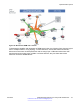


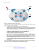
Table Of Contents
- Contents
- Chapter 1: Introduction
- Chapter 2: New in this release
- Chapter 3: Network design fundamentals
- Chapter 4: Hardware fundamentals and guidelines
- Chapter 5: Optical routing design
- Chapter 6: Platform redundancy
- Chapter 7: Link redundancy
- Chapter 8: Layer 2 loop prevention
- Chapter 9: Layer 2 switch clustering and SMLT
- Chapter 10: Layer 3 switch clustering and RSMLT
- Chapter 11: Layer 3 switch clustering and multicast SMLT
- Chapter 12: Spanning tree
- Chapter 13: Layer 3 network design
- Chapter 14: SPBM design guidelines
- Chapter 15: IP multicast network design
- Multicast and VRF-Lite
- Multicast and MultiLink Trunking considerations
- Multicast scalability design rules
- IP multicast address range restrictions
- Multicast MAC address mapping considerations
- Dynamic multicast configuration changes
- IGMPv3 backward compatibility
- IGMP Layer 2 Querier
- TTL in IP multicast packets
- Multicast MAC filtering
- Guidelines for multicast access policies
- Split-subnet and multicast
- Protocol Independent Multicast-Sparse Mode guidelines
- Protocol Independent Multicast-Source Specific Multicast guidelines
- Multicast for multimedia
- Chapter 16: System and network stability and security
- Chapter 17: QoS design guidelines
- Chapter 18: Layer 1, 2, and 3 design examples
- Glossary

SMLT
If your existing edge configuration uses SMLT, you can maintain that SMLT-based resiliency for
services configured on the vIST peer switches. SPBM requires that you upgrade both vIST peer to
the current release and identify two VLANs to use as B-VLANs. SPBM then automatically creates a
virtual backbone MAC for the vIST pair, and advertises it with IS-IS. By operating two SPBM
switches in switch clustering (SMLT) mode, you can achieve redundant connectivity between the C-
VLAN domain and the SPBM infrastructure. This configuration allows the dual homing of any
traditional link aggregation capable device into an SPBM network.
SMLT with IP multicast over Fabric Connect
Layer 2 access switches use IGMP Snooping to prune multicast traffic. In IP multicast over Fabric
Connect, BEBs are the IGMP queriers, therefore access switches forward multicast data from the
senders as well as IGMP control messages from receivers to the BEBs.
1. When a sender transmits multicast data to the Layer 2 access switch that has an MLT to the
switch cluster, the multicast data is hashed towards one or the other BEBs in the switch
cluster.
2. The receiving BEB allocates a Data I-SID and sends a TLV update on the primary B-VLAN,
to announce the availability of the stream to its neighbors.
3. The BEB propagates the TLV update through the SPBM fabric in an LSP, so all BEBs are
aware of this stream availability.
4. The sender information is also synchronized over the vIST to the peer switch.
5. Then the peer switch allocates a Data I-SID for the multicast stream, and sends a TLV
update on the secondary B-VLAN to announce the stream availability.
Campus architecture
For migration purposes, you can add SPBM to an existing network that has SMLT configured. In
fact, if there are other protocols already running in the network, such as Open Shortest Path First
(OSPF), you can leave them in place too. SPBM uses IS-IS, and operates independently from other
protocols. However, Avaya recommends that you eventually eliminate SMLT in the core and
eliminate other unnecessary protocols. This reduces the complexity of the network and makes it
much simpler to maintain and troubleshoot.
Whether or not you configure SMLT in the core, the main point to remember is that SPBM separates
services from the infrastructure. For example, in a large campus, a user may need access to other
sites or data centers. With SPBM you can grant that access by associating the user to a specific I-
SID. With this mechanism, the user can work without getting access to confidential information of
another department.
The following figure depicts a topology where the BEBs in the edge and data center distribution
nodes are configured in SMLT clusters. Prior to implementing SPBM, the core nodes would also
have been configured as SMLT clusters. When migrating SPBM onto this network design, it is
important to note that you can deploy SPBM over the existing SMLT topology without network
interruption. After the SPBM infrastructure is in place, you can create VSN services over SPBM or
migrate them from the previous end-to-end SMLT-based design.
Reference architectures
June 2015 Network Design Reference for Avaya VSP 4000 Series 105
Comments on this document? infodev@avaya.com