
Design Reference
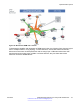


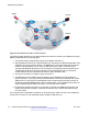
Table Of Contents
- Contents
- Chapter 1: Introduction
- Chapter 2: New in this release
- Chapter 3: Network design fundamentals
- Chapter 4: Hardware fundamentals and guidelines
- Chapter 5: Optical routing design
- Chapter 6: Platform redundancy
- Chapter 7: Link redundancy
- Chapter 8: Layer 2 loop prevention
- Chapter 9: Layer 2 switch clustering and SMLT
- Chapter 10: Layer 3 switch clustering and RSMLT
- Chapter 11: Layer 3 switch clustering and multicast SMLT
- Chapter 12: Spanning tree
- Chapter 13: Layer 3 network design
- Chapter 14: SPBM design guidelines
- Chapter 15: IP multicast network design
- Multicast and VRF-Lite
- Multicast and MultiLink Trunking considerations
- Multicast scalability design rules
- IP multicast address range restrictions
- Multicast MAC address mapping considerations
- Dynamic multicast configuration changes
- IGMPv3 backward compatibility
- IGMP Layer 2 Querier
- TTL in IP multicast packets
- Multicast MAC filtering
- Guidelines for multicast access policies
- Split-subnet and multicast
- Protocol Independent Multicast-Sparse Mode guidelines
- Protocol Independent Multicast-Source Specific Multicast guidelines
- Multicast for multimedia
- Chapter 16: System and network stability and security
- Chapter 17: QoS design guidelines
- Chapter 18: Layer 1, 2, and 3 design examples
- Glossary

Figure 47: SPBM ring topology with shared data centers
Reference architectures
SPBM has a straightforward architecture that simply forwards encapsulated C-MACs across the
backbone. Because the B-MAC header stays the same across the network, there is no need to
swap a label or perform a route lookup at each node. This architecture allows the frame to follow the
most efficient forwarding path from end to end.
The following reference architectures illustrate SPBM with multiple VSP and ERS systems in a
network. For information about solution-specific architectures like Video Surveillance or Data Center
implementation using the VSP 4000, see
Solution specific reference architectures on page 115.
The following figure shows the MAC-in-MAC SPBM domain with BEBs on the boundary and BCBs
in the core.
SPBM design guidelines
102 Network Design Reference for Avaya VSP 4000 Series June 2015
Comments on this document? infodev@avaya.com