
Installation Instructions


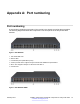

Table Of Contents
- Contents
- Chapter 1: Introduction
- Chapter 2: New in Release 4.1
- Chapter 3: Safety and equipment care
- Chapter 4: SFP
- SFP transceivers
- SFP specifications
- SFP labels
- General SFP specifications
- Supported SFP transceivers
- 1000BASE-T SFP specifications
- 1000BASE-SX DDI SFP specifications
- 1000BASE-LX DDI SFP specifications
- 1000BASE-XD DDI 1310 nm SFP specifications
- 1000BASE-XD DDI 1550 nm SFP specifications
- 1000BASE-ZX DDI 1550 nm SFP specifications
- 1000BASE-XD DDI CWDM (40 km) SFP specifications
- 1000BASE-ZX DDI CWDM 70 km SFP specifications
- 1000BASE-BX bidirectional SFP transceivers
- 1000BASE-EX DDI SFP specifications
- 100BASE-FX SFP specifications
- Chapter 5: SFP+
- SFP+ transceivers
- SFP+ specifications
- SFP+ labels
- General SFP+ specifications
- Supported SFP+ transceivers
- 10GBASE-LR/LW SFP+ specifications
- 10GBASE-LR/LW SFP+ high temperature (-5 °C to +85 °C) specifications
- 10GBASE-ER/EW SFP+ specifications
- 10GBASE-SR/SW SFP+ specifications
- 10GBASE-SR/SW SFP+ high temperature (0 °C to +85 °C) specifications
- 10GBASE-ZR/ZW SFP+ specifications
- 10GBASE-LRM SFP+ specifications
- 10GBASE-CX specifications
- 10GBASE-ER CWDM SFP+ specifications
- Chapter 6: Translations of safety messages
- Class A electromagnetic interference warning statement
- Electrostatic discharge caution statement
- Laser eye safety danger statement
- Laser eye safety connector inspection danger statement
- Connector cleaning safety danger statement
- Optical fiber damage warning statement
- Optical fiber connector damage warning statement
- SFP damage warning statement
- Appendix A: Port numbering
- Glossary

Appendix A: Port numbering
Port numbering
A port number includes the slot location of the module in the chassis, as well as the port position.
The following diagrams illustrate the components on the front panels of the Avaya VSP 4000
switches.
Figure 4: VSP 4850GTS
1. VSP 4000 USB cover
2. Switch LEDs
3. 10/100/1000 ports (LEDs above ports)
4. Combo port SFP slots. Supports Avaya 1G SFPs and 100Base low speed SFPs.
5. SFP+ slots. Supports Avaya’s 1G SFPs and 10G SFP+s.
6. Console Port
Figure 5: VSP 4850GTS-PWR+
February 2015 Installing Transceivers and Optical components on Avaya VSP 4000 59
Comments? infodev@avaya.com