
Installation Instructions


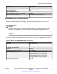


Table Of Contents
- Contents
- Chapter 1: Introduction
- Chapter 2: New in this document
- Chapter 3: Optical routing design
- Chapter 4: Safety and equipment care information
- Chapter 5: SFP
- SFP transceivers
- SFP specifications
- SFP labels
- General SFP specifications
- Supported SFP transceivers
- Autonegotiation
- 1000BASE-SX (LC) SFP specifications
- 1000BASE-SX (MT-RJ) SFP specifications
- 1000BASE-LX SFP specifications
- 1000BASE-XD CWDM SFP specifications
- 1000BASE-ZX CWDM (LC) SFP specifications
- 1000BASE-T SFP specifications
- 1000BASE-SX DDI SFP specifications
- 1000BASE-LX DDI SFP specifications
- 1000BASE-XD DDI 1310 nm SFP specifications
- 1000BASE-XD DDI 1550 nm SFP specifications
- 1000BASE-ZX DDI 1550 nm SFP specifications
- 1000BASE-XD DDI CWDM (40 km) SFP specifications
- 1000BASE-ZX DDI CWDM 70 km SFP specifications
- 1000BASE-BX bidirectional SFP transceivers
- 1000BASE-EX DDI SFP specifications
- 100BASE-FX SFP specifications
- Chapter 6: SFP+
- SFP+ transceivers
- SFP+ specifications
- SFP+ labels
- General SFP+ specifications
- Supported SFP+ transceivers
- 10GBASE-LR/LW SFP+ specifications
- 10GBASE-LR/LW SFP+ high temperature (-5 °C to +85 °C) specifications
- 10GBASE-ER/EW SFP+ specifications
- 10GBASE-SR/SW SFP+ specifications
- 10GBASE-SR/SW SFP+ high temperature (0 °C to +85 °C) specifications
- 10GBASE-ZR/ZW SFP+ specifications
- 10GBASE-CX specifications
- 10GBASE-ER CWDM DDI SFP+ specifications
- 10GBASE-LRM SFP+ specifications
- 10GBASE-ZR CWDM DDI SFP+ specifications
- 10GBASE-BX SFP+ specifications
- SFP+ cable assembly specifications
- Chapter 7: QSFP+
- Chapter 8: Translations of safety messages
- Class A electromagnetic interference warning statement
- Electrostatic discharge caution statement
- Laser eye safety danger statement
- Laser eye safety connector inspection danger statement
- Connector cleaning safety danger statement
- Optical fiber damage warning statement
- Optical fiber connector damage warning statement
- SFP damage warning statement
- Glossary

Note:
The Avaya VSP 4000 does not support 40 Gbps QSFP+ transceivers because the VSP 4000
devices do not have any QSFP+ ports. However, the VSP 4000 series supports the four SFP+
10-gigabit ends of the Direct Attach Breakout Cable (BOC) assembly.
The following table identifies the part numbers for specific cable assembly lengths.
Cable type Cable
length
Minimum software version Part number
VSP 4000 VSP 7200 VSP 8200 VSP 8400
Passive copper
breakout cable
1 meter 4.2.1 4.2.1 4.2.0 4.2.0 AA1404033-E6
Passive copper
breakout cable
3 meter 4.2.1 4.2.1 4.2.0 4.2.0 AA1404035-E6
Passive copper
breakout cable
5 meter 4.2.1 4.2.1 4.2.0 4.2.0 AA1404036-E6
Active optical
breakout cable
10 meter 4.2.1 4.2.1 4.2.1 4.2.1 AA1404041-E6
QSFP+ to QSFP+ 40–gigabit direct attach cable specifications
The QSFP+ to QSFP+ 40–gigabit Direct Attach Cable (DAC) assembly directly connects two QSFP
+ ports. For more information, see the IEEE 802.3ba 40GBASE-CR4 cable assembly specification
standard.
The following table identifies the part numbers for specific cable assembly lengths.
Cable
type
Cable
length
Minimum software version Part number
VSP 4000 VSP 7200 VSP 8200 VSP 8400
Passive
flexi-
DAC
(TAA)
0.5 meter N/A 4.2.1 4.0.0 4.2.0 AA1404037-E6
Passive
copper
DAC
1 meter N/A 4.2.1 4.0.0 4.2.0 AA1404029-E6
Passive
copper
DAC
3 meter N/A 4.2.1 4.0.0 4.2.0 AA1404031-E6
Passive
copper
DAC
5 meter N/A 4.2.1 4.0.0 4.2.0 AA1404032-E6
Active
optical
DAC
10 meter N/A 4.2.1 4.2.1 4.2.1 AA1404028-E6
QSFP+
April 2016 Installing Transceivers and Optical Components on Avaya VSP Operating System
Software 80
Comments on this document? infodev@avaya.com