
Installation Instructions


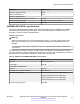


Table Of Contents
- Contents
- Chapter 1: Introduction
- Chapter 2: New in this document
- Chapter 3: Optical routing design
- Chapter 4: Safety and equipment care information
- Chapter 5: SFP
- SFP transceivers
- SFP specifications
- SFP labels
- General SFP specifications
- Supported SFP transceivers
- Autonegotiation
- 1000BASE-SX (LC) SFP specifications
- 1000BASE-SX (MT-RJ) SFP specifications
- 1000BASE-LX SFP specifications
- 1000BASE-XD CWDM SFP specifications
- 1000BASE-ZX CWDM (LC) SFP specifications
- 1000BASE-T SFP specifications
- 1000BASE-SX DDI SFP specifications
- 1000BASE-LX DDI SFP specifications
- 1000BASE-XD DDI 1310 nm SFP specifications
- 1000BASE-XD DDI 1550 nm SFP specifications
- 1000BASE-ZX DDI 1550 nm SFP specifications
- 1000BASE-XD DDI CWDM (40 km) SFP specifications
- 1000BASE-ZX DDI CWDM 70 km SFP specifications
- 1000BASE-BX bidirectional SFP transceivers
- 1000BASE-EX DDI SFP specifications
- 100BASE-FX SFP specifications
- Chapter 6: SFP+
- SFP+ transceivers
- SFP+ specifications
- SFP+ labels
- General SFP+ specifications
- Supported SFP+ transceivers
- 10GBASE-LR/LW SFP+ specifications
- 10GBASE-LR/LW SFP+ high temperature (-5 °C to +85 °C) specifications
- 10GBASE-ER/EW SFP+ specifications
- 10GBASE-SR/SW SFP+ specifications
- 10GBASE-SR/SW SFP+ high temperature (0 °C to +85 °C) specifications
- 10GBASE-ZR/ZW SFP+ specifications
- 10GBASE-CX specifications
- 10GBASE-ER CWDM DDI SFP+ specifications
- 10GBASE-LRM SFP+ specifications
- 10GBASE-ZR CWDM DDI SFP+ specifications
- 10GBASE-BX SFP+ specifications
- SFP+ cable assembly specifications
- Chapter 7: QSFP+
- Chapter 8: Translations of safety messages
- Class A electromagnetic interference warning statement
- Electrostatic discharge caution statement
- Laser eye safety danger statement
- Laser eye safety connector inspection danger statement
- Connector cleaning safety danger statement
- Optical fiber damage warning statement
- Optical fiber connector damage warning statement
- SFP damage warning statement
- Glossary

cable or configuration changes. Cable cuts are the dominant cause of link failure and have
been observed to occur on average 4.39 times per thousand sheath miles per year.
Table 42: 40GBASE-ER4 operating ranges
Required operating range
2 m to 30 km
2 m to 40 km
Interoperation
40GBASE-ER4 and 40GBASE-LR4 QSFP+ transceivers can interoperate with a properly-
engineered link. It requires the cabling (channel) characteristics for 40GBASE-LR4 to be met, with
the exception of the maximum and minimum channel insertion loss values, as shown in the following
table, for the two link directions separately.
Direction Min. loss Max. loss Unit
40GBASE-LR4
transmitter to 40GBASE-
ER4 receiver
7.5 14.2 dB
40GBASE-ER4
transmitter to 40GBASE-
LR4 receiver
2.2 11 dB
QSFP+ cable assembly specifications
This section provides cable assembly specifications for the supported 40–gigabit QSFP+ transceiver
module.
Important:
The VSP switches operate in forgiving mode for QSFP+ direct attach cables, which means that
the switch will bring up the port operationally when using non-Avaya direct attach cables. Avaya
does not provide support for operational issues related to these DACs, but they will operate and
the port link will come up.
QSFP+ breakout cable specifications
This section provides technical specifications for the supported breakout cables (BOC).
QSFP+ to four SFP+ 10–gigabit BOC
The QSFP+ to four SFP+ 10–gigabit direct attach breakout cable assembly directly connects one
QSFP+ port to four SFP+ ports.
QSFP+ cable assembly specifications
April 2016 Installing Transceivers and Optical Components on Avaya VSP Operating System
Software 79
Comments on this document? infodev@avaya.com