
Installation Instructions


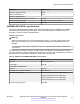


Table Of Contents
- Contents
- Chapter 1: Introduction
- Chapter 2: New in this document
- Chapter 3: Optical routing design
- Chapter 4: Safety and equipment care information
- Chapter 5: SFP
- SFP transceivers
- SFP specifications
- SFP labels
- General SFP specifications
- Supported SFP transceivers
- Autonegotiation
- 1000BASE-SX (LC) SFP specifications
- 1000BASE-SX (MT-RJ) SFP specifications
- 1000BASE-LX SFP specifications
- 1000BASE-XD CWDM SFP specifications
- 1000BASE-ZX CWDM (LC) SFP specifications
- 1000BASE-T SFP specifications
- 1000BASE-SX DDI SFP specifications
- 1000BASE-LX DDI SFP specifications
- 1000BASE-XD DDI 1310 nm SFP specifications
- 1000BASE-XD DDI 1550 nm SFP specifications
- 1000BASE-ZX DDI 1550 nm SFP specifications
- 1000BASE-XD DDI CWDM (40 km) SFP specifications
- 1000BASE-ZX DDI CWDM 70 km SFP specifications
- 1000BASE-BX bidirectional SFP transceivers
- 1000BASE-EX DDI SFP specifications
- 100BASE-FX SFP specifications
- Chapter 6: SFP+
- SFP+ transceivers
- SFP+ specifications
- SFP+ labels
- General SFP+ specifications
- Supported SFP+ transceivers
- 10GBASE-LR/LW SFP+ specifications
- 10GBASE-LR/LW SFP+ high temperature (-5 °C to +85 °C) specifications
- 10GBASE-ER/EW SFP+ specifications
- 10GBASE-SR/SW SFP+ specifications
- 10GBASE-SR/SW SFP+ high temperature (0 °C to +85 °C) specifications
- 10GBASE-ZR/ZW SFP+ specifications
- 10GBASE-CX specifications
- 10GBASE-ER CWDM DDI SFP+ specifications
- 10GBASE-LRM SFP+ specifications
- 10GBASE-ZR CWDM DDI SFP+ specifications
- 10GBASE-BX SFP+ specifications
- SFP+ cable assembly specifications
- Chapter 7: QSFP+
- Chapter 8: Translations of safety messages
- Class A electromagnetic interference warning statement
- Electrostatic discharge caution statement
- Laser eye safety danger statement
- Laser eye safety connector inspection danger statement
- Connector cleaning safety danger statement
- Optical fiber damage warning statement
- Optical fiber connector damage warning statement
- SFP damage warning statement
- Glossary

Parameter Specification
Stressed receiver sensitivity, each lane at 10.3125
Gbps.
–9.6 dBm
Receive input optical power (damage threshold per lane) 3.3 dBm
40GBASE-LM4 QSFP+ specifications
This transceiver operates up to 80 meters on 50 µm MMF cable plant and is compliant with channel
insertion loss specified in IEEE standard 802.3-2012, Table 52-10, for 2000 (OM3) or 4700 MHz*km
(OM4) 50 um multimode fiber.
Note:
Channel insertion loss includes connectors.
The 40GBASE-LM4 QSFP+ transceiver supports a link configuration of a backbone cable between
patch panels with one jumper from the transceiver to the patch panel at each end. All ends support
duplex LC connectors. Connector return loss requirement is 20 dB or greater (reflectance –20 dB or
less).
Other 10GBASE-S transceivers and link parameters do not apply, as the LM4 operates in the 1310
nm region. The 40GBASE-LM4 QSFP+ transceiver contains four transmitters where the signal is
internally multiplexed to the Tx port and contains four receivers where the signal is internally
demultiplexed at the Rx port.
The 40GBASE-LM4 QSFP+ transceiver replaces a 40GBASE-SR4 QSFP+ transceiver for
applications up to 80 meters. The transceiver uses one pair of MMF fibers and a duplex LC
connector versus the eight fibers with MPO/MTP connectors that are used with the 40GBASE-SR4
QSFP+ transceiver. The transceiver is not interoperable with 40GBASE-SR4 or 10GBASE-SR
transceivers.
The following table lists the transmitter, cable plant, and receiver specifications for the 40GBASE-
LM4 QSFP+ transceiver. The part number is AA1404002-E6.
Parameter Specification
Data rate (nominal) 4 X 10 Gbps
Nominal transmitter center wavelengths 1271, 1291, 1311, 1331
Link distance (OM3 and OM4) Up to 80 m maximum
Operating temperature range 0 °C to +70 °C
Transmitter characteristics
Maximum total average launch power 10.3 dBm
Maximum average launch power, each lane 4.3 dBm
Maximum average launch power of OFF transmitter –30 dBm
Maximum optical return loss tolerance 20 dB
Applicable cable plant
Maximum insertion loss, including connectors 2.6 dB (OM3) or 2.9 dB (OM4)
Table continues…
QSFP+
April 2016 Installing Transceivers and Optical Components on Avaya VSP Operating System
Software 76
Comments on this document? infodev@avaya.com