
Installation Instructions


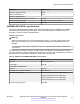


Table Of Contents
- Contents
- Chapter 1: Introduction
- Chapter 2: New in this document
- Chapter 3: Optical routing design
- Chapter 4: Safety and equipment care information
- Chapter 5: SFP
- SFP transceivers
- SFP specifications
- SFP labels
- General SFP specifications
- Supported SFP transceivers
- Autonegotiation
- 1000BASE-SX (LC) SFP specifications
- 1000BASE-SX (MT-RJ) SFP specifications
- 1000BASE-LX SFP specifications
- 1000BASE-XD CWDM SFP specifications
- 1000BASE-ZX CWDM (LC) SFP specifications
- 1000BASE-T SFP specifications
- 1000BASE-SX DDI SFP specifications
- 1000BASE-LX DDI SFP specifications
- 1000BASE-XD DDI 1310 nm SFP specifications
- 1000BASE-XD DDI 1550 nm SFP specifications
- 1000BASE-ZX DDI 1550 nm SFP specifications
- 1000BASE-XD DDI CWDM (40 km) SFP specifications
- 1000BASE-ZX DDI CWDM 70 km SFP specifications
- 1000BASE-BX bidirectional SFP transceivers
- 1000BASE-EX DDI SFP specifications
- 100BASE-FX SFP specifications
- Chapter 6: SFP+
- SFP+ transceivers
- SFP+ specifications
- SFP+ labels
- General SFP+ specifications
- Supported SFP+ transceivers
- 10GBASE-LR/LW SFP+ specifications
- 10GBASE-LR/LW SFP+ high temperature (-5 °C to +85 °C) specifications
- 10GBASE-ER/EW SFP+ specifications
- 10GBASE-SR/SW SFP+ specifications
- 10GBASE-SR/SW SFP+ high temperature (0 °C to +85 °C) specifications
- 10GBASE-ZR/ZW SFP+ specifications
- 10GBASE-CX specifications
- 10GBASE-ER CWDM DDI SFP+ specifications
- 10GBASE-LRM SFP+ specifications
- 10GBASE-ZR CWDM DDI SFP+ specifications
- 10GBASE-BX SFP+ specifications
- SFP+ cable assembly specifications
- Chapter 7: QSFP+
- Chapter 8: Translations of safety messages
- Class A electromagnetic interference warning statement
- Electrostatic discharge caution statement
- Laser eye safety danger statement
- Laser eye safety connector inspection danger statement
- Connector cleaning safety danger statement
- Optical fiber damage warning statement
- Optical fiber connector damage warning statement
- SFP damage warning statement
- Glossary

Table 38: General QSFP+ specifications
Parameter Specification
Dimensions (H x W x D) 8.5 x 18.35 x 72.4 mm (0.33 x
0.72 x 2.85 in.), unless otherwise
stated.
Note:
The length of the pull tab
latch varies depending on the
vendor and the body, with a
length of 125 to 132 mm
(4.92 to 5.20 in.).
Connectors 40GBASE–SR4 QSFP+ MPO or MTP
40GBASE–LR4 QSFP+ LC Duplex
Storage temperature –40 °F (–4 °C) to 185 °F (85 °C)
Operating temperature 23 °F (−5 °C) to 158 °F (70 °C)
Supported QSFP+ transceivers
The following section provides specifications for supported QSFP+ transceivers.
40GBASE-SR4 QSFP+ specifications
The 40GBASE-SR4 4x10GBASE-SR transceiver provides a high-speed link at an aggregate
signaling rate.
Important:
Not all Avaya networking products support the 4x10GBASE-SR mode of operation.
The 40GBASE-SR4 transceiver supports the MPO connector and the duplex LC connector.
Typically, the MPO connector has two alignment pins, which keeps the connector and the fibers
aligned to the mating cable.
For more information about the 40GBASE-SR4 4x10GBASE-SR QSFP+ transceiver, including test
and measurement information, see the IEEE 802.3-2012 standard.
The following table lists the specifications for the 40GBASE-SR4 4x10GBASE-SR QSFP+
transceiver. The part number of this QSFP+ transceiver is AA1404005-E6.
Table 39: 40GBASE-SR4 4x10GBASE-SR QSFP+ transceiver specifications
Parameter
Specification
Line rate 10.3125 Gbps
Center wavelength range 840 to 860 nanometers
Table continues…
QSFP+ transceiver specifications
April 2016 Installing Transceivers and Optical Components on Avaya VSP Operating System
Software 73
Comments on this document? infodev@avaya.com