
Installation Instructions


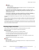

Table Of Contents
- Contents
- Chapter 1: Introduction
- Chapter 2: New in this document
- Chapter 3: Optical routing design
- Chapter 4: Safety and equipment care information
- Chapter 5: SFP
- SFP transceivers
- SFP specifications
- SFP labels
- General SFP specifications
- Supported SFP transceivers
- Autonegotiation
- 1000BASE-SX (LC) SFP specifications
- 1000BASE-SX (MT-RJ) SFP specifications
- 1000BASE-LX SFP specifications
- 1000BASE-XD CWDM SFP specifications
- 1000BASE-ZX CWDM (LC) SFP specifications
- 1000BASE-T SFP specifications
- 1000BASE-SX DDI SFP specifications
- 1000BASE-LX DDI SFP specifications
- 1000BASE-XD DDI 1310 nm SFP specifications
- 1000BASE-XD DDI 1550 nm SFP specifications
- 1000BASE-ZX DDI 1550 nm SFP specifications
- 1000BASE-XD DDI CWDM (40 km) SFP specifications
- 1000BASE-ZX DDI CWDM 70 km SFP specifications
- 1000BASE-BX bidirectional SFP transceivers
- 1000BASE-EX DDI SFP specifications
- 100BASE-FX SFP specifications
- Chapter 6: SFP+
- SFP+ transceivers
- SFP+ specifications
- SFP+ labels
- General SFP+ specifications
- Supported SFP+ transceivers
- 10GBASE-LR/LW SFP+ specifications
- 10GBASE-LR/LW SFP+ high temperature (-5 °C to +85 °C) specifications
- 10GBASE-ER/EW SFP+ specifications
- 10GBASE-SR/SW SFP+ specifications
- 10GBASE-SR/SW SFP+ high temperature (0 °C to +85 °C) specifications
- 10GBASE-ZR/ZW SFP+ specifications
- 10GBASE-CX specifications
- 10GBASE-ER CWDM DDI SFP+ specifications
- 10GBASE-LRM SFP+ specifications
- 10GBASE-ZR CWDM DDI SFP+ specifications
- 10GBASE-BX SFP+ specifications
- SFP+ cable assembly specifications
- Chapter 7: QSFP+
- Chapter 8: Translations of safety messages
- Class A electromagnetic interference warning statement
- Electrostatic discharge caution statement
- Laser eye safety danger statement
- Laser eye safety connector inspection danger statement
- Connector cleaning safety danger statement
- Optical fiber damage warning statement
- Optical fiber connector damage warning statement
- SFP damage warning statement
- Glossary

Chapter 3: Optical routing design
Optical routing design
The Avaya optical routing system uses coarse wavelength division multiplexing (CWDM) in a grid of
eight optical wavelengths. Use the Avaya optical routing system to maximize bandwidth on a single
optical fiber. This chapter provides optical routing system information that you can use to help
design your network.
Related links
Optical routing system components on page 13
Dispersion considerations for long reach on page 15
Optical routing system components
Small Form Factor Pluggable (SFP) transceivers transmit optical signals from gigabit Ethernet ports
to multiplexers in a passive optical shelf.
Multiplexers combine multiple wavelengths traveling on different fibers onto a single fiber. At the
receiver end of the link, demultiplexers separate the wavelengths and route them to different fibers,
which terminate at separate CWDM devices. The following figure shows multiplexer and
demultiplexer operations.
Important:
For clarity, the following figure shows a single fiber link with signals traveling in one direction
only. A duplex connection requires communication in the reverse direction as well.
April 2016 Installing Transceivers and Optical Components on Avaya VSP Operating System
Software 13
Comments on this document? infodev@avaya.com