
Installation Instructions


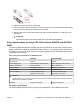

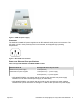
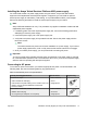
Table Of Contents
- Installation Job Aid (English) for Avaya VSP 4000 4850GTS
- How to get help
- Notices
- Safety messages
- Before you begin
- Installing the Avaya Virtual Services Platform 4000 on a table or shelf
- Installing the Avaya Virtual Services Platform 4000 in an equipment rack
- Installing SFP transceivers
- Removing SFP transceivers
- Power specifications for Avaya VSP 4000 switches 4850GTS and 4850GTS-PWR+
- Avaya Virtual Services Platform power supply power specification
- Installing the Avaya Virtual Services Platform 4000 power supply
- Connecting to AC power

3. Slide the transceiver from the module slot.
4. If the transceiver does not slide easily from the module slot, use a gentle side-to-side rocking
motion while firmly pulling the transceiver from the slot.
5. Attach a dust cover over the fiber-optic bores and store the transceiver in a safe place until
you need it.
Important:
Discard transceivers in accordance with the proper laws and regulations.
Power specifications for Avaya VSP 4000 switches 4850GTS and 4850GTS-
PWR+
The following table describes the regulatory AC power specifications for the Avaya Virtual Services
Platform 4000 Series 4850GTS and 4850GTS-PWR+ switches. The regulatory power specifications
are based on the maximum rated capacity of the power supplies and are not based on typical power
consumption which is lower.
Table 1: AC power specifications for 4850GTS series
Specifications 4850GTS 4850GTS-PWR+
Input Current 5A/2.5 A 12A/6A
Input Voltage (rms) 100 to 240 VAC at 50 to 60 Hz 100 to 240 VAC at 50 to 60 Hz
Power Consumption 94.6 W maximum 248 W maximum
Thermal Rating 323 BTU/hr maximum 508 BTU/hr maximum
Inrush Current 40 A maximum 70 A maximum
Turn on Condition 1 second maximum after
application of AC power
1 second maximum after
application of AC power
Important:
12-volt output rise time, from 10 to 90 percent, must be the maximum of 50 ms and monotonic under all
defined input and output conditions.
Efficiency 70 percent minimum 70 percent minimum
DC power specifications
The following table describes the DC power supply specifications for the 4850GTS-DC model.
July 2015 Installation Job Aid (English) for Avaya VSP 4000 4850GTS 7