
Installation Instructions


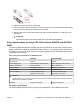

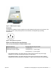
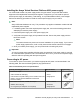
Table Of Contents
- Installation Job Aid (English) for Avaya VSP 4000 4850GTS
- How to get help
- Notices
- Safety messages
- Before you begin
- Installing the Avaya Virtual Services Platform 4000 on a table or shelf
- Installing the Avaya Virtual Services Platform 4000 in an equipment rack
- Installing SFP transceivers
- Removing SFP transceivers
- Power specifications for Avaya VSP 4000 switches 4850GTS and 4850GTS-PWR+
- Avaya Virtual Services Platform power supply power specification
- Installing the Avaya Virtual Services Platform 4000 power supply
- Connecting to AC power

Caution:
On a factory-supplied 4850GTS series switch, do not remove the USB device cover or
the USB device from the slot. Removing the USB device affects system operation
and may even prevent the system from booting up successfully. Ensure that the USB
device is inserted in the system at all times with the USB cover on.
2. Attach the included rubber footpads on the bottom of the switch at the locations indicated.
3. Set the switch on a table or shelf as illustrated below. Allow at least 2 inches (5.1
centimeters) on each side for proper ventilation and at least 5 inches (12.7 centimeters) at
the back for power cord clearance.
July 2015 Installation Job Aid (English) for Avaya VSP 4000 4850GTS 4