
Installation Instructions


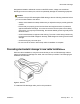


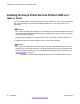
Table Of Contents
- Contents
- Chapter 1: Avaya Virtual Services Platform 4000 regulatory information and safety precautions
- International regulatory statements of conformity
- National electromagnetic compliance (EMC) statements of compliance
- FCC statement (USA only)
- ICES statement (Canada only)
- CE marking statement (Europe only)
- European Union and European Free Trade Association (EFTA) notice
- VCCI statement (Japan/Nippon only)
- BSMI statement (Taiwan only)
- MIC notice (Republic of Korea only)
- National Safety Statements of Compliance
- EN 60950 statement
- NOM statement (Mexico only)
- Información NOM (unicamente para México)
- Denan statement (Japan/Nippon only)
- National Environmental Statements of Compliance
- Restriction on Hazardous Substances Directive Compliance Statement
- WEEE Directive Compliance Statement
- Notices
- Chapter 2: Introduction
- Chapter 3: New in this release
- Chapter 4: Hardware compatibility
- Chapter 5: Installing the Avaya Virtual Services Platform 4000
- Installation fundamentals
- Electrostatic discharge
- Environmental requirements
- Package contents
- Installing the Avaya Virtual Services Platform 4000 on a table or shelf
- Installing the Avaya Virtual Services Platform 4000 in an equipment rack
- Cable requirements for the Avaya Virtual Services Platform 4000
- Installation and removal of Small Form-factor Pluggable (SFP) transceivers
- RJ-45 connector pin assignments
- Console port pin assignments
- Power specifications for the Avaya Virtual Services Platform 4000
- Avaya Virtual Services Platform power supply power specification
- Installing the Avaya Virtual Services Platform 4000 power supply
- Connect AC power
- Check Light Emitting Diode (LED) on the Avaya Virtual Services Platform 4000
- Chapter 6: Translations of safety messages

Environmental
requirement
Avaya Virtual Services Platform 4000 models
• An adequate power source is within 6 feet (1.83 meters) of
the switch. One 15-amp circuit is required for each power
supply.
• At least 2 inches (5.08 centimeters) of clearance on each
side of the switch unit for ventilation.
• Adequate clearance at the front and rear of the switch for
access to cables.
Warning:
To avoid bodily injury from hazardous electrical shock and current, never remove the top of
the device. No user-serviceable components are inside. For a translation of this statement,
see
Translations of safety messages on page 49.
Package contents
The following describes the components that are provided with each switch. If any components
are missing, contact the switch vendor.
1. Avaya Virtual Services Platform 4000
2. Rack-mounting hardware that includes:
• Rack-mount brackets
• Screws to attach brackets to the switch
• Screws to attach the switch to the equipment rack
3. Rubber footpads
4. AC power cord
5. Documentation
Note:
Cable trays can be provided as an option.
Package contents
Installation February 2014 29