
Installation Instructions


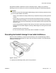


Table Of Contents
- Contents
- Chapter 1: Avaya Virtual Services Platform 4000 regulatory information and safety precautions
- International regulatory statements of conformity
- National electromagnetic compliance (EMC) statements of compliance
- FCC statement (USA only)
- ICES statement (Canada only)
- CE marking statement (Europe only)
- European Union and European Free Trade Association (EFTA) notice
- VCCI statement (Japan/Nippon only)
- BSMI statement (Taiwan only)
- MIC notice (Republic of Korea only)
- National Safety Statements of Compliance
- EN 60950 statement
- NOM statement (Mexico only)
- Información NOM (unicamente para México)
- Denan statement (Japan/Nippon only)
- National Environmental Statements of Compliance
- Restriction on Hazardous Substances Directive Compliance Statement
- WEEE Directive Compliance Statement
- Notices
- Chapter 2: Introduction
- Chapter 3: New in this release
- Chapter 4: Hardware compatibility
- Chapter 5: Installing the Avaya Virtual Services Platform 4000
- Installation fundamentals
- Electrostatic discharge
- Environmental requirements
- Package contents
- Installing the Avaya Virtual Services Platform 4000 on a table or shelf
- Installing the Avaya Virtual Services Platform 4000 in an equipment rack
- Cable requirements for the Avaya Virtual Services Platform 4000
- Installation and removal of Small Form-factor Pluggable (SFP) transceivers
- RJ-45 connector pin assignments
- Console port pin assignments
- Power specifications for the Avaya Virtual Services Platform 4000
- Avaya Virtual Services Platform power supply power specification
- Installing the Avaya Virtual Services Platform 4000 power supply
- Connect AC power
- Check Light Emitting Diode (LED) on the Avaya Virtual Services Platform 4000
- Chapter 6: Translations of safety messages

1. Connect the ground lug on the ESD discharge cable to a safe and suitable earth
ground.
2. Connect all RJ-45 cable connectors to the female RJ-45 connector of the ESD
discharge cable for at least 5 seconds, and then connect each RJ-45 cable
connector to the switch.
3. Leave cables connected to the networking equipment. After you connect cables to
networking equipment, the cables do not build up charge.
Environmental requirements
The following table provides the environmental requirements for the individual switches in this
series. Ensure that the area where you install the switch and where it operates meets these
requirements.
Table 5: Avaya Virtual Services Platform 4000 environmental requirements
Environmental
requirement
Avaya Virtual Services Platform 4000 models
Ambient Temperature 0°C to 50°C (32°F to 104°F), continuous operation
Operating Temperature 0°C to 50°C (32°F to 104°F)
Storage Temperature –40°C to 85°C (-13°F to 158°F)
Operating Humidity 0 to 95 percent noncondensing
Operating Relative
Humidity
10 to 90 percent noncondensing
Storage Relative Humidity 10 to 90 percent noncondensing
Maximum Operating
Altitude
3,048m (10 000 feet) above sea level
Altitude 0 to 3,048m (0 to 10,000ft) above sea level
Storage Altitude 0 to 12,192m (0 to 40,000ft) above sea level
Acoustic Noise Less than or equal to 45 db at 35°C and less than or equal to
57 db at 50°C. The temperature is allowed to have ±3.5°C
deviation around the threshold of 35C, (measurement
methods based on ISO 7779).
Miscellaneous Operating
Considerations
• No heat sources such as hot air vents or direct sunlight near
the switch.
• No sources of severe electromagnetic interference near the
switch.
• No excessive dust in the environment.
Installing the Avaya Virtual Services Platform 4000
28 Installation February 2014
Comments? infodev@avaya.com