
Design Reference
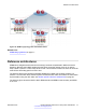


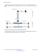
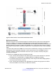


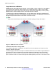
Table Of Contents
- Contents
- Chapter 1: Introduction
- Chapter 2: New in Release 4.0.50
- Chapter 3: New in Release 4.0.40
- Chapter 4: New in Release 4.0
- Chapter 5: Network design fundamentals
- Chapter 6: Hardware fundamentals and guidelines
- Chapter 7: Optical routing design
- Chapter 8: Platform redundancy
- Chapter 9: Link redundancy
- Chapter 10: Layer 2 loop prevention
- Chapter 11: Spanning tree
- Chapter 12: Layer 3 network design
- Chapter 13: SPBM design guidelines
- Chapter 14: IP multicast network design
- Multicast and VRF-Lite
- Multicast and MultiLink Trunking considerations
- Multicast scalability design rules
- IP multicast address range restrictions
- Multicast MAC address mapping considerations
- Dynamic multicast configuration changes
- IGMPv3 backward compatibility
- IGMP Layer 2 Querier
- TTL in IP multicast packets
- Multicast MAC filtering
- Guidelines for multicast access policies
- Multicast for multimedia
- Chapter 15: System and network stability and security
- Chapter 16: QoS design guidelines
- Chapter 17: Layer 1, 2, and 3 design examples
- Chapter 18: Software scaling capabilities
- Chapter 19: Supported standards, RFCs, and MIBs
- Glossary

The following figure uses IP shortcuts that route VLANs. There is no I-SID configuration and no
Layer 3 virtualization between the edge distribution and the core. This is normal IP forwarding to the
BEB.
Figure 39: IP shortcut scenario to move traffic between data centers
The following figure uses Layer 3 VSNs to route VRFs between the edge distribution and the core.
The VRFs are attached to I-SIDs and use Layer 3 virtualization.
SPBM design guidelines
86 Network Design Reference for Avaya VSP 4000 Series December 2014
Comments? infodev@avaya.com