
Design Reference


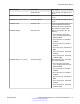
Table Of Contents
- Contents
- Chapter 1: Introduction
- Chapter 2: New in Release 4.0.50
- Chapter 3: New in Release 4.0.40
- Chapter 4: New in Release 4.0
- Chapter 5: Network design fundamentals
- Chapter 6: Hardware fundamentals and guidelines
- Chapter 7: Optical routing design
- Chapter 8: Platform redundancy
- Chapter 9: Link redundancy
- Chapter 10: Layer 2 loop prevention
- Chapter 11: Spanning tree
- Chapter 12: Layer 3 network design
- Chapter 13: SPBM design guidelines
- Chapter 14: IP multicast network design
- Multicast and VRF-Lite
- Multicast and MultiLink Trunking considerations
- Multicast scalability design rules
- IP multicast address range restrictions
- Multicast MAC address mapping considerations
- Dynamic multicast configuration changes
- IGMPv3 backward compatibility
- IGMP Layer 2 Querier
- TTL in IP multicast packets
- Multicast MAC filtering
- Guidelines for multicast access policies
- Multicast for multimedia
- Chapter 15: System and network stability and security
- Chapter 16: QoS design guidelines
- Chapter 17: Layer 1, 2, and 3 design examples
- Chapter 18: Software scaling capabilities
- Chapter 19: Supported standards, RFCs, and MIBs
- Glossary

Model number Part number Description
10GBASE-ZR/ZW AA1403016-E6 1550 nm SMF. The range is up to
70 km.
10GBASE-ZR CWDM DDI AA1403161-E6 1471 nm SMF. The range is up to
70 km.
AA1403162-E6 1491 nm SMF. The range is up to
70 km.
AA1403163-E6 1511 nm SMF. The range is up to
70 km.
AA1403164-E6 1531 nm SMF. The range is up to
70 km.
AA1403165-E6 1551 nm SMF. The range is up to
70 km.
AA1403166-E6 1571 nm SMF. The range is up to
70 km.
AA1403167-E6 1591 nm SMF. The range is up to
70 km.
AA1403168-E6 1611 nm SMF. The range is up to
70 km.
Optical power considerations
When you connect the device to collocated equipment, ensure that enough optical attenuation exists
to avoid overloading the receivers of each device. You must consider the minimum attenuation
requirement based on the specifications of third-party equipment. For more information about
minimum insertion losses for Avaya optical products, see Installing Transceivers and Optical
components on the Avaya Virtual Services Platform 4000 Series, NN46251-301.
Dispersion considerations for long reach
Precise engineering of transmission links is difficult; specifications and performance are often
unknown, undocumented, or impractical to measure before equipment installation. Moreover, the
skills required to perform rigorous link budget analysis are extensive. Fortunately, a simple,
straightforward approach can assure robust link performance for most optical fiber systems in which
you use Avaya switches and routers.
This method uses an optical power budget, the difference between transmitter power and receiver
sensitivity, to determine whether the installed link can operate with low bit error ratio for extended
periods. The power budget must accommodate the sum of link loss (that is, attenuation), dispersion,
and system margin, described in the following paragraphs.
Link losses are the sum of cabled fiber loss, splices, and connectors, often with an allocation for
additional connectors. Cabled fiber loss is wavelength and installation dependent, and is typically in
the range of 0.20 to 0.5 dB/km. See the cable plant owner or operator for specifications of the cable
Hardware fundamentals and guidelines
30 Network Design Reference for Avaya VSP 4000 Series December 2014
Comments? infodev@avaya.com